2-20
Chapter 2 Installation of this Device
2-2-7 1/2B Remote Attachment (JTE/JTH Model)
(1) Attachment Overview
(i) Attachment dimensions
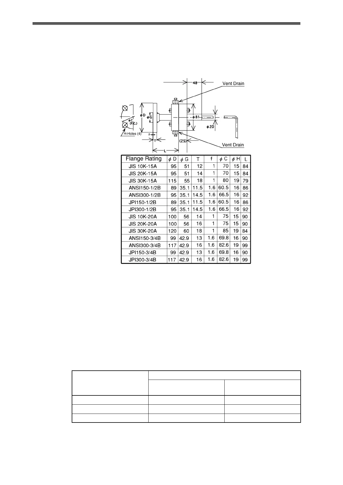
Figure 2-25 shows an assembly dimensions diagram.
(Unit: mm)
Figure 2-25. 1/2B Remote Adapter Assembly Diagram and Dimensions
(ii) Attachment method
(1) 1/2B remote adapter attachment check
Confirm that the pressure-receiving parts at the ends of the capillary tubes and the adapter are
securely fastened together using four sets of bolts and nuts. If they are not fastened together,
or if they are loose, fasten them together securely. When doing so, check the state of the anti-
stick grease, and apply grease as necessary to prevent sticking. In addition, remove any foreign
materials, as these may also cause sticking.
Table 2-3. Tightening Torque
Bolt/Nut Material
Bolt/Nut Tightening Torque (N·m)
Adapter Flange Material
SCS14A/SUSF316
Adapter Flange Material
PVC
SUS304 10±1 7±0.5
SUS630 20±1 -
Carbon Steel 20±1 7±0.5