A-32
Appendix A Maintenance and Troubleshooting of this Device
In this case, the index value under normal operating conditions is similar to that with clogging,
or the index value is almost the same even when clogging occurs. In either case, it is necessary to
examine the cause and to minimize this effect. Use the following guidelines for adjustment.
Guidelines for parameter adjustment
Phenomenon Adjustment
Since the process variable fluctuates and there is
always low-frequency pressure fluctuation, the
value of the index is small even under normal
operating conditions. The standard deviation is
relatively large.
Increase the Press Freq Filter Constant in steps
of 0.02–0.05.
The PV does not change and the standard
deviation is also small. The frequency of the
original pressure fluctuation is low and the index
value is small. (The reference index value is 0.1
or less under normal operating conditions.) Fluid
viscosity is high.
Change the Press Freq Index Sensor Selection.
If the present value is “DP, 120 ms”, set it to
“DP, 240 ms,” and if the present value is “DP,
240 ms,” set it to “DP, 360 ms.”
The magnitude and frequency of the original
pressure fluctuation are acceptable. (The
reference index value is 0.2 or more under
normal operating conditions.) However, the
value is almost the same when there is clogging.
Decrease the Press Freq Filter Constant in
steps of 0.02–0.05.
A4-4-7 Clogging simulation test cannot be conducted.
When the clogging simulation test cannot be conducted, only the index value data under normal
operating conditions (index values collected in section A4-4-2) can be used to determine the
threshold value. When many index values can be collected, calculate the average value (μ)
and standard deviation (σ), and determine the threshold value based on μ ± nσ. To eliminate
misinformation, a value from 4 to 6 is recommended for n. The threshold value can also be
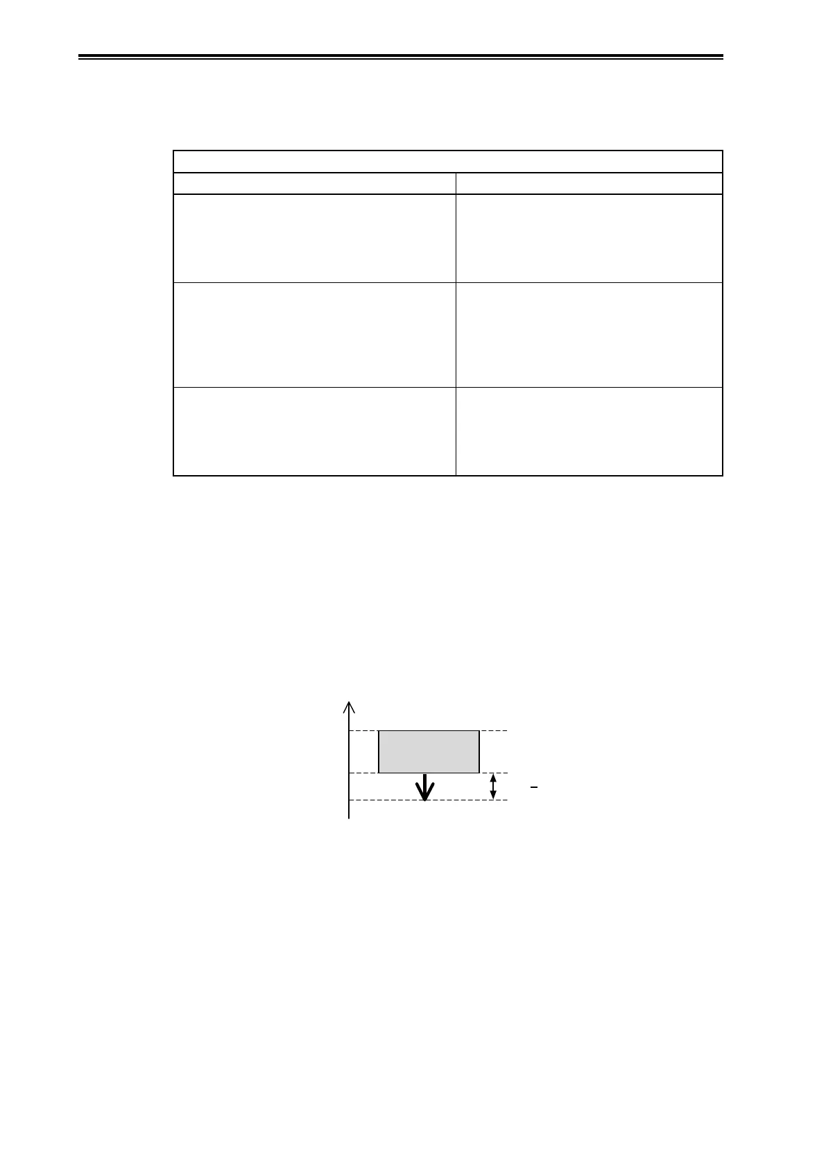
determined using the maximum (xmax) and minimum (xmin) index values. For example, the
threshold value should be set to a value that is no more than (xmax−xmin)/2 from the minimum
value, as shown in the figure below.
max
Index value
Threshold
value(Low)
Index value range
under the normal
operating conditions
Note that the threshold value determined using only the index value data under normal operating
conditions is not always appropriate. The index value may become smaller than the threshold value
due to causes other than clogging, or the index value may not become smaller than the threshold
value even when clogging occurs. Observe changes in the index value for a short period after the
threshold value has been determined, and then check that the index value does not become smaller
than the threshold value under normal operating conditions, and that the difference between the
correct value range and threshold value is not large. Revise the threshold value when necessary.