2-5
Chapter 2 Installation of this Device
2-2 Installation
2-2-1 Installation Dimensions
See the dimensions diagram (in the specifications sheet or delivery specifications) for this device.
2-2-2 Installation Location
See the general installation conditions in 2-1-1.
2-2-3 Transmitter Body Installation
(1) Components Required for Installation
In order to install this device, have the following items ready.
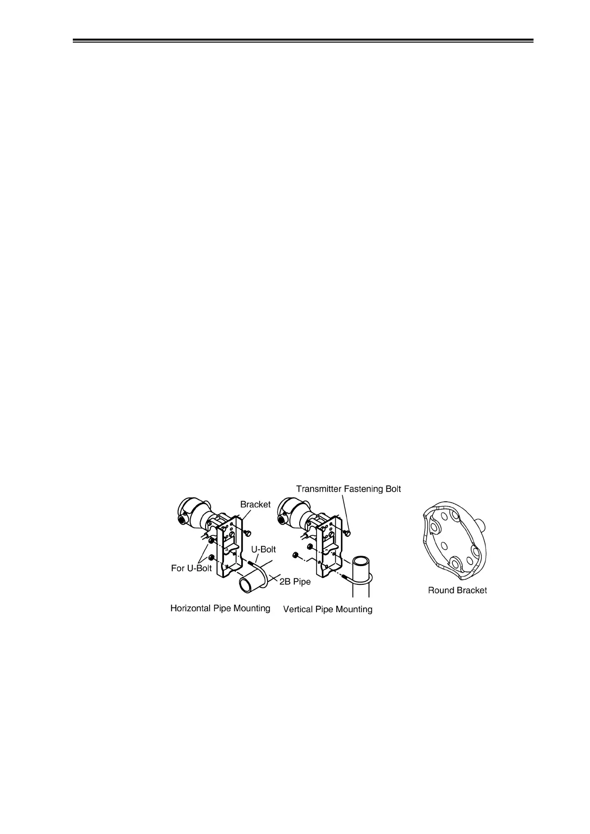
• Mounting bracket (U-bolts, nuts, and mounting bolts provided) ---- optional
Select one of the two types of brackets.
Bracket (left diagram in Figure 2-2)
Round bracket (right diagram in Figure 2-2)
* The round bracket allows a more compact installation than was possible in the past.
• 2B pipe
(2) Installation Method
(i) Pipe stanchion installation
Using the mounting bracket (selectable from two types), fasten the device to the vertical or
horizontal 50A (2B) pipe with a U-bolt. There are four bolt holes on the rear surface of the pressure
receiving main body; mount the bracket there. The pipe should be fastened securely to
its foundation, with no unsteadiness.
(ii) Line mount installation
If the pipe is 50A (2B), attach it in the same way as for the pipe stanchion. If the pipe is not
50A (2B), attach a 50A (2B) pipe to the line pipe.
Figure 2-2. Transmitter Body Installation
* The flange type (JTC type) is attached directly to the tank.