2-34
Chapter 2 Installation of this Device
2-3-3 Liquid Level Measurement Piping (JTD/JTG Model)
Warning
When doing the piping work, ensure that the connections between the connecting pipe
parts and the transmitter and three-way manifold valve are able to maintain a reliable
seal. If sealing is inadequate, there is a danger that the measured fluid will leak out and
cause scalding and other harmful health effects. If the measured fluid is harmful to the
human body, take safety measures such as wearing goggles or a mask so that it does not
adhere to the skin or the eyes, become inhaled, etc.
(1) Piping
(i) Introduction
The method of measuring the liquid level in the tank using a JTD model transmitter differs depending
on whether the tank is open or sealed. In addition, if the tank is sealed, the piping method also differs
depending on whether the gas seal method (dry leg) or the liquid seal method (wet leg) is used.
Measuring the liquid level in the tank using a JTG model transmitter is in general performed on
anopen tank.
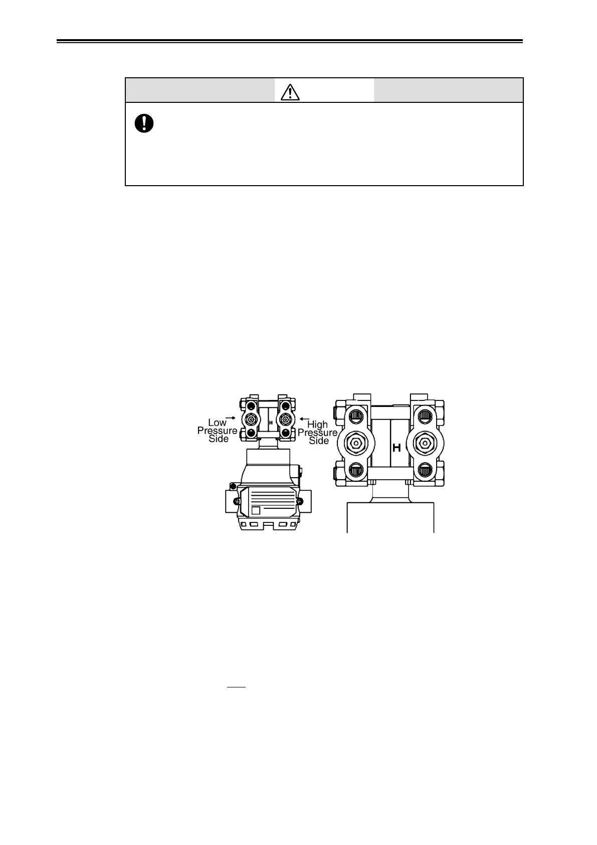
(ii) High pressure side mark on this device
An “H” is displayed on the high pressure side of the main unit of this device to indicate high
pressure, so be sure to check this during piping in order to avoid mistakes. The side without a mark
is the low pressure side.
Figure 2-40. Mark on High Pressure Side of Main Unit
(iii) Caution
In the range that appears on the nameplate at the time of shipping, if the amount of suppression is
more than 1/2 the span, the positions of H and L switch. In that case, H will be on the left side, and
the H mark will be on the rear side. In this case, do the process piping so as to connect the high
pressure to the side without the H stamp.
Example: When range is -50 to +20 kPa
Suppression quantity 50 kPa
Span 70 kPa
50 >
70
= 35 is the result,
2
so the amount of suppression is higher, and thus the high pressure side will be on the left side.