2-33
Chapter 2 Installation of this Device
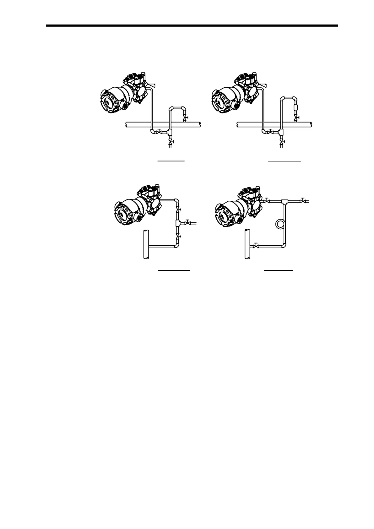
(ii) Piping method
The piping method differs depending on the state of the measured fluid, indicator location,
pipeline, etc. A typical piping example is illustrated below. Run the piping as shown below.
Process
ProcessProcess
Process
Master Valve
Master ValveMaster Valve
Master
Valve
Siphon
Drain Valve
Drain ValveDrain Valve
Drain Valve
Manual
Master
Valve
Manual
Master
Valve
Manual
Master
Valve
Manual
Master Valve
D. Steam
C. Wet Gas
B. Dry Gas
A. Liquid
Figure 2-39. Pressure Measurement Piping Example
(iii) Auxiliary equipment
(1) Oil sealing and air purging
If it is not possible to guide the measured fluid directly to this device due to suspension,
high viscosity, high temperature, corrosiveness, etc., use sealing or purging. For information
regarding sealing and purging methods, please consult with the relevant personnel
at our company.
(2) Throttle valves for pulsation flow prevention
If there is high-speed pulsation flow in the process fluid, or high levels of pressure fluctuation,
fluctuations can be suppressed by installing a throttle or the like in the connecting pipe.