2-21
Chapter 2 Installation of this Device
(2)
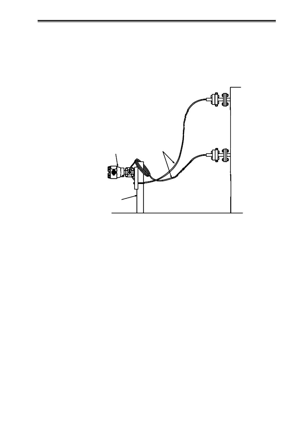
Attachment to process side flanges
Figure 2-26 shows an example of attachment to the tank. For information regarding flange
attachment, see section 2-2-4. The minimum bending diameter of the capillary tubes should be
about 5 cm. For information regarding capillary tube handling, see section 2-2-4. In addition,
depending on the properties of the measured fluid, the fluid may in some cases solidify in the
adapter and impede measurement. In such cases, keep the area around the adapter sufficiently
warm so that the measured fluid does not solidify.
Tank
Capillary
Tubes
Transmitter
Pipe
Stanchion
Figure 2-26. Instrumentation example for the Tank