2-30
Chapter 2 Installation of this Device
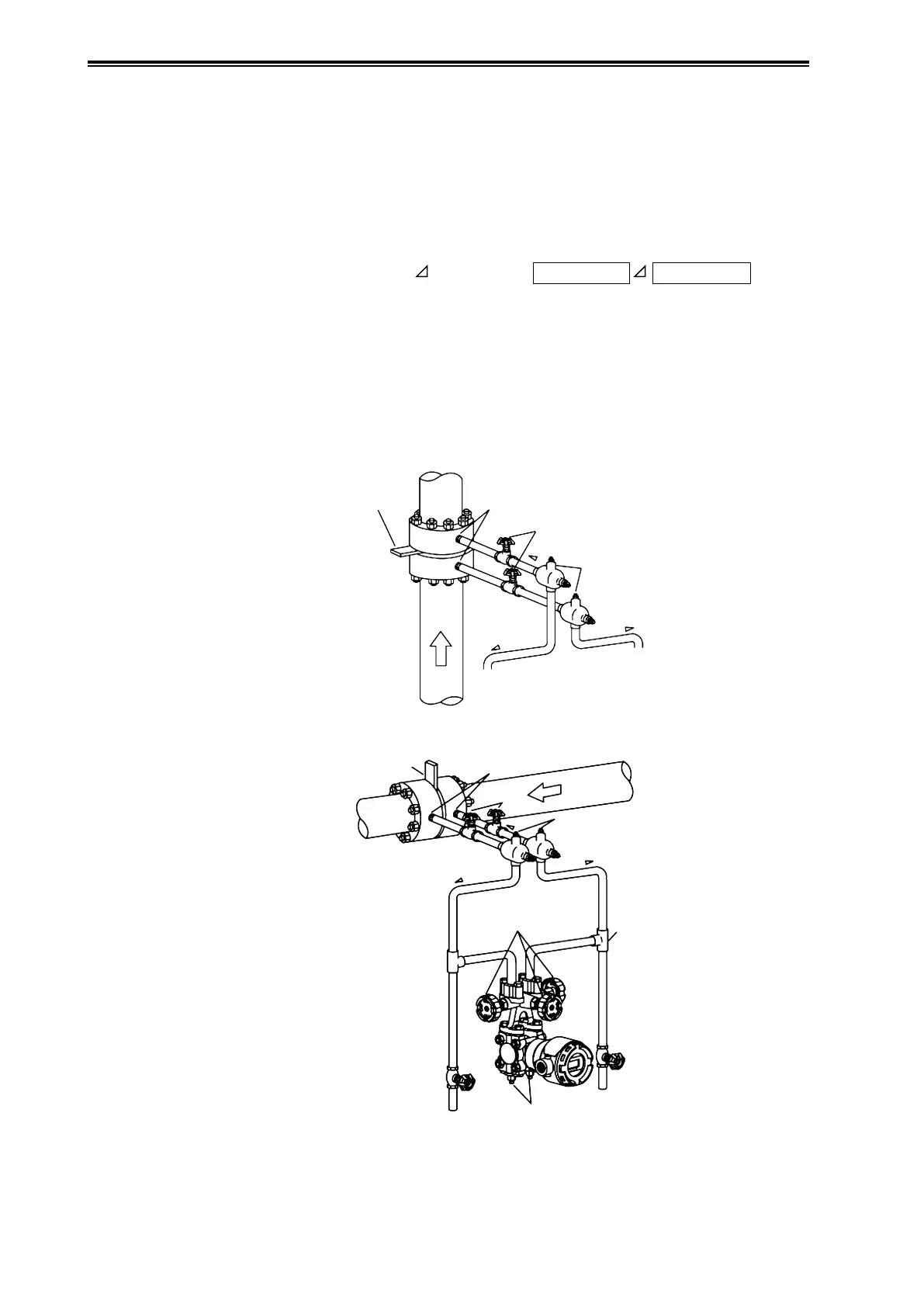
(3) Vapor Flow Rate Measurement Piping
(i) Recommended piping example
A typical piping example is illustrated below. With this vapor flow rate measurement piping,
the device is installed lower than the differential pressure output port.
Be sure to implement the following items.
• Depending on the measured fluid, create an incline of at least 1/10 in the differential pressure
output pipes so that drains will clear.
Meaning of incline symbol
in the diagram:
Low position
High position
• After doing the piping work, confirm that there are no pressure leaks in the connecting pipes,
the three-way manifold valve, the transmitter, etc.
• For the purpose of connecting pipe maintenance, use T-joints to attach drain valves.
• If the process has a vertical pipe, installing the condensers different heights as shown in the
diagram prevents zero drift in the differential pressure gauge, which otherwise would occur
readily. Incidentally, in this case it is not possible to perform zero adjustment using the three-
way manifold valve.
Master Valves
Master
Valves
Drain Plugs
Drain
Valve
Drain
Valve
Three-Way Manifold Valve
Orice
Orice
Dierential Pressure Outlets
Dierential
Pressure Outlets
T-Joint
High
Pressure Side
High
Pressure
Side
Low
Pressure Side
Condensers
Condensers
Low
Pressure
Side
Incline
Incline
Incline
Incline
Incline
Process Pipe (Vertical)
Figure 2-36. Vapor Flow Rate Measurement Piping Example