2-29
Chapter 2 Installation of this Device
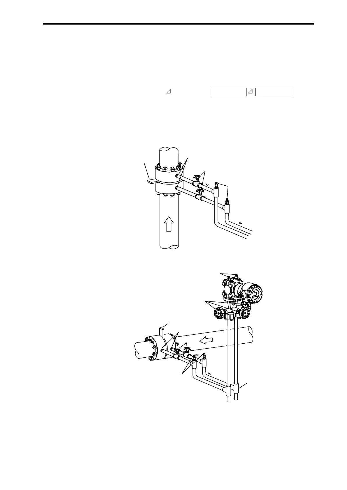
(ii) Recommended piping, example 2
A typical piping example in which the device is higher than the differential pressure output port of
the process pipe is shown below.
Be sure to implement the following items.
• Depending on the measured fluid, create an incline of at least 1/10 in the differential pressure
output pipes so that drains, vents, etc., will clear.
Meaning of incline symbol
in the diagram:
Low position
High position
• Install gas vent plugs at locations where gas in connecting pipes exits.
• After doing the piping work, confirm that there are no pressure leaks in the connecting pipes,
the three-way manifold valve, the transmitter, etc.
• For the purpose of connecting pipe maintenance, use T-joints to attach drain valves.
Master Valves
Master
Valves
Gas Vent Plugs
Gas Vent Plugs
Gas Vent Plugs
Three-Way
Manifold Valve
Orice
Orice
Dierential
Pressure Outlets
Dierential Pressure Outlets
T-Joint
High
Pressure
Side
High
Pressure
Side
Low
Pressure
Side
Low
Pressure
Side
Incline
Incline
Incline
Process Pipe (Vertical)
Figure 2-35. Example of Piping for Gas Flow Rate Measurement