2-28
Chapter 2 Installation of this Device
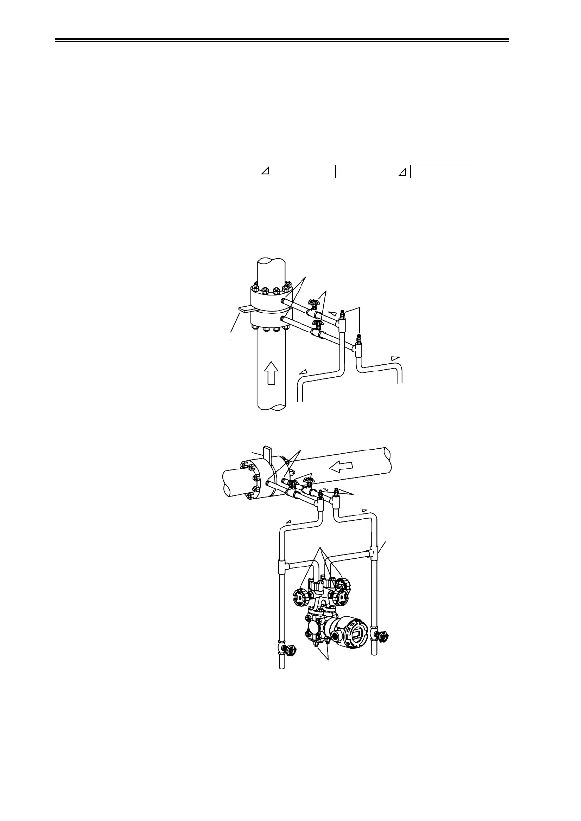
(2) Liquid or Gas Flow Rate Measurement Piping
(i) Example of recommended piping for liquid flow rate measurement
A typical piping example in which the device is lower than the differential pressure output port on
the process pipe.
Be sure to implement the following items.
• Depending on the measured fluid, create an incline in the differential pressure output pipes so
that drains, vents, etc., will clear.
Meaning of incline symbol
in the diagram:
Low position
High position
• Install gas vent plugs at locations where gas in connecting pipes exits.
• After doing the piping work, confirm that there are no pressure leaks in the connecting pipes,
the three-way manifold valve, the transmitter, etc.
• For the purpose of connecting pipe maintenance, use T-joints to attach drain valves.
Master Valves
Master
Valve
Orice
Orice
Three-Way
Manifold Valve
Drain
Plugs
Drain
Valve
Drain
Valve
Dierential Pressure Outlets
Dierential Pressure
Outlets
High
Pressure
Side
High
Pressure
Side
Low
Pressure
Side
Low
Pressure
Side
Incline
Incline
Incline
Incline
Incline
Incline
Gas Vent Plugs
Gas Vent Plugs
T-Joint
Process Pipe (Vertical)
Figure 2-34. Example of Piping for Liquid Flow Rate Measurement