2-27
Chapter 2 Installation of this Device
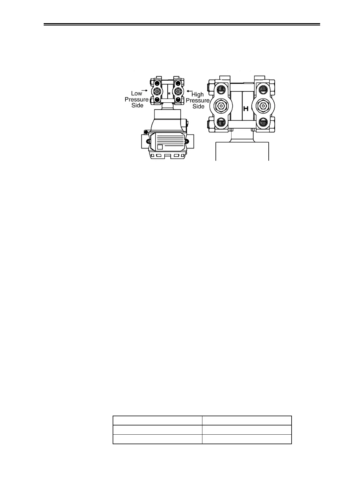
(ii) High pressure side display on this device
An “H” is displayed on the high pressure side of the main unit of this device to indicate high
pressure, so be sure to check this during piping in order to avoid mistakes. The side without a mark
is the low pressure side.
Figure 2-33. Mark on High Pressure Side of Main Unit
(iii) Selection of pipes to use
For connecting pipes from the process, select pipe schedule numbers and nominal thicknesses in
accordance with process side selection criteria (conditions such as process pressure). Diameter
1/2B, schedule number 80 steel pipes are one example of connecting pipes which are commonly
used.
(iv) Required parts example
When doing the piping work, refer to the piping example diagram, and have the following parts
ready. Select the rating, material, etc., of each part based on process side selection standards.
• Three-Way Manifold Valve
• Pipes
• Master Valves
• Unions or Flanges
• T-Joints
• Drain Valves
• Gas Vent Plugs
• Condenser (only for connecting valves for vapor flow rate measurement)
(v) Adapter flange
When doing the piping work, follow the table below for tightening torque when using an adapter
flange. Note that the bolts that fasten the adapter flange are loose when shipped.
Table 2-4. Adapter Flange Tightening Torque
Material / Bolt Size Tightening Torque (N·m)
Carbon Steel 20±2
SUS304/316 10±1