4-10
Chapter 4 Maintenance and Troubleshooting of this Device
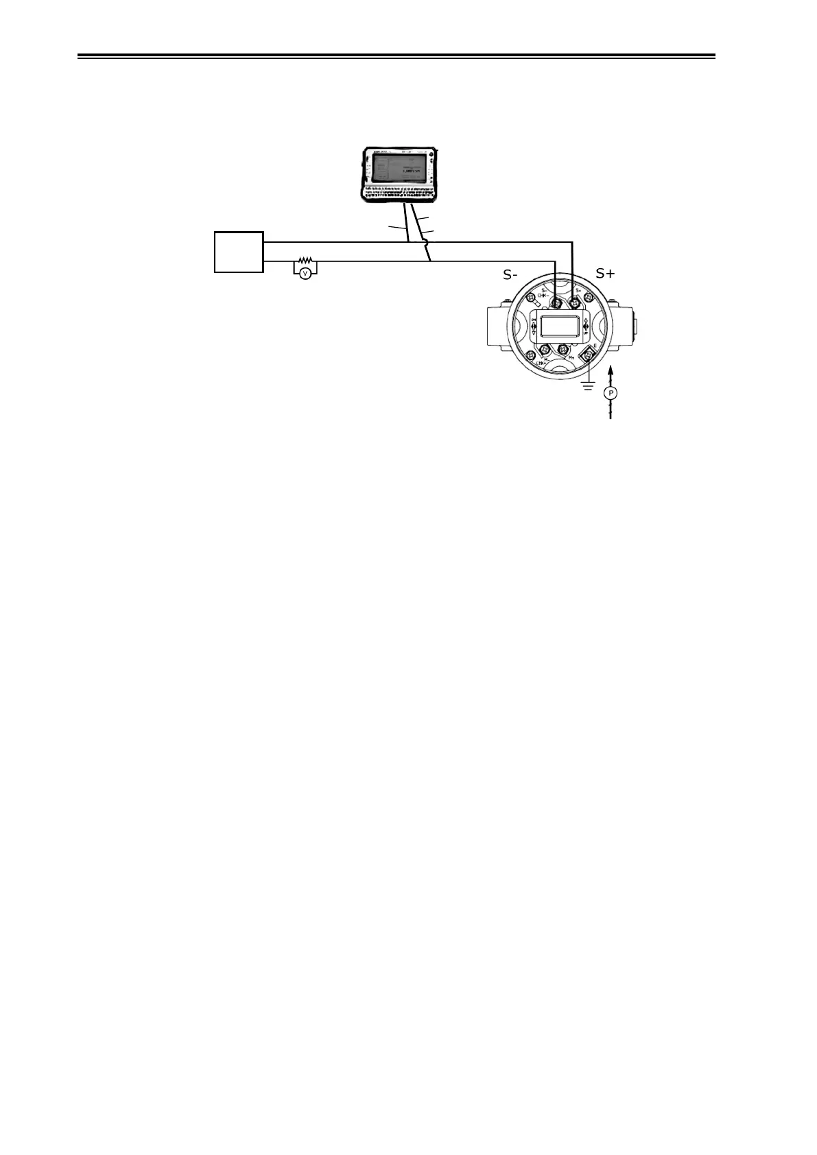
(5) Wiring and Piping During Calibration
In general, the following wiring and piping should be employed.
+
−
Red Wire
Voltmeter
Communication Cable
Black Wire
Standard
Pressure
Generator
Connects to pressure
inlet of cover ange
Precision Resistor
DC Power
Supply
24V
Figure 4-3. Wiring and piping during Calibration
(6) Checking the Setting Range
See the operation manuals for the respective communicators.
CommStaff Instruction Manual (HART5) Section 2-6 / (HART7) Section 1-3
HART Communicator Operation Manual (HART5) Section 3-2-1 / (HART7) Section 3-2-1
(7) Measurement Range Calibration Procedure
See the operation manuals for the respective communicators.
CommStaff Instruction Manual (HART5) Section 4-2 / (HART7) Section 3-2
HART Communicator Operation Manual (HART5) Section 3-2-8 / (HART7) Section 3-3-2