2-8
Chapter 2 Installation of this Device
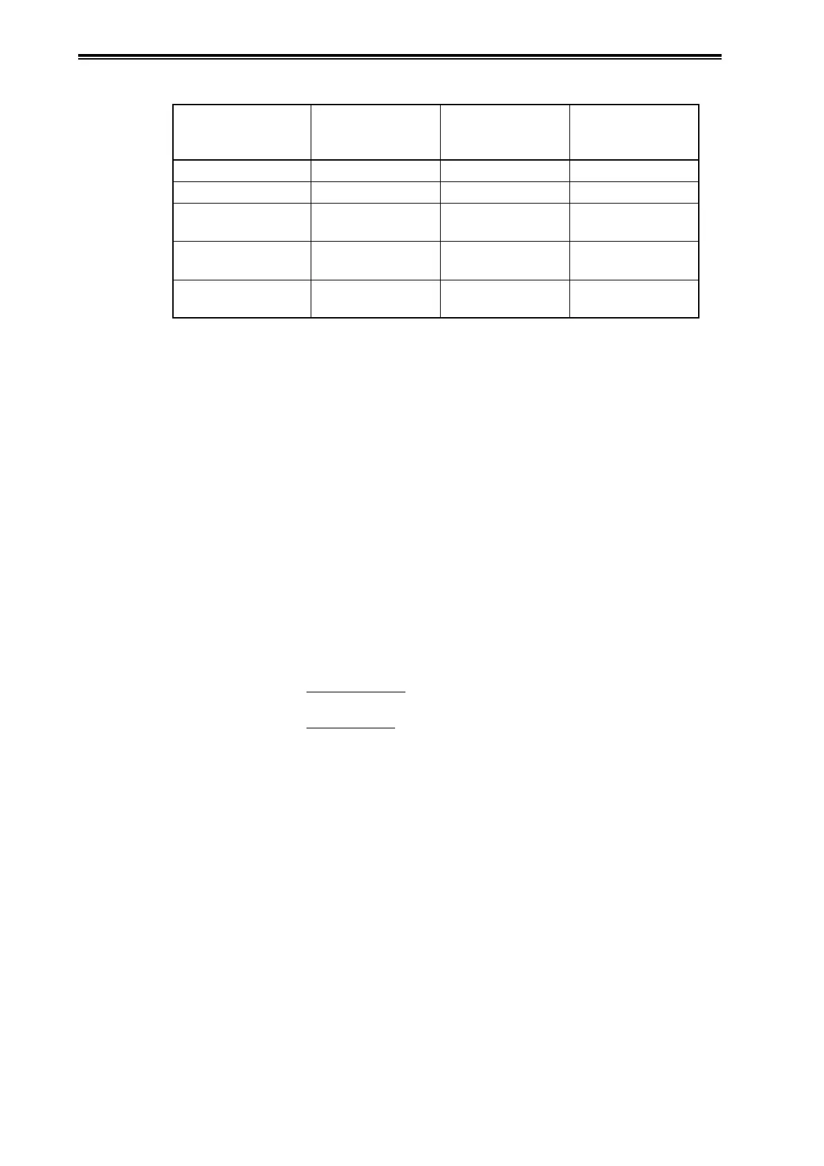
Table 2-1. Allowable Pressure Low Limit Example
Sealed Liquid
Specific Gravity
ρ'
Allowable Pressure
Low Limit
P (kPa abs)
Contact Liquid
Temperature Range
°C
General-purpose 0.935 2 -40 to +40
For high-temperature 1.07 2 -5 to +90
For high-temperature
vacuum
1.07 0.133 -5 to +100
For high-temperature
high-vacuum
1.09 0.133 10 to +250
For oxygen, for
chlorine
1.87 53 -5 to +40
Precautions for allowable pressure low limit
• If the contact liquid temperature range in Table 2-1 is exceeded, the allowable pressure low limit
will change as well, so refer to the specifications and calculate the value.
• If the contact liquid ambient temperature range with which the allowable pressure low limit was
calculated is narrower than the ambient temperature range during normal operation, take steps
to ensure that the ambient temperature range of the installation area falls within this contact
liquid ambient temperature range.
(v) Calculation example: case in which general-purpose sealed liquid,
remote seal type transmitter JTE is used in a vacuum application
Liquid Temperature: 25 °C
Allowable pressure low limit (P): 2 kPa abs. (15 mm Hg abs.)
Sealed Liquid Specific Gravity (ρ'): 0.935
Tank internal pressure (P0): 3 kPa abs. (low limit)
In order to satisfy the transmitter specifications, substituting into
h ≤
(P0 - P) × 102
yields
ρ'
h ≤
(3 - 2) × 102
= 109 mm
0.935
Accordingly, the transmitter can be attached at a location up to 109 mm above the tank lower
flange.
Precaution regarding negative pressure: If the above conditions are not satisfied, the diaphragm
surface will be pulled by negative pressure exceeding the usage range, resulting in the sealed liquid
reaching saturation vapor pressure and causing bubbles to form. If the negative pressure becomes
even greater, the diaphragm may undergo buckling and become damaged. Recognizing that it may
not necessarily be clear to customers what values to use in installation location calculations, we
recommend that the transmitter body be installed at least 100 mm lower than the lower flange.