2-13
Chapter 2 Installation of this Device
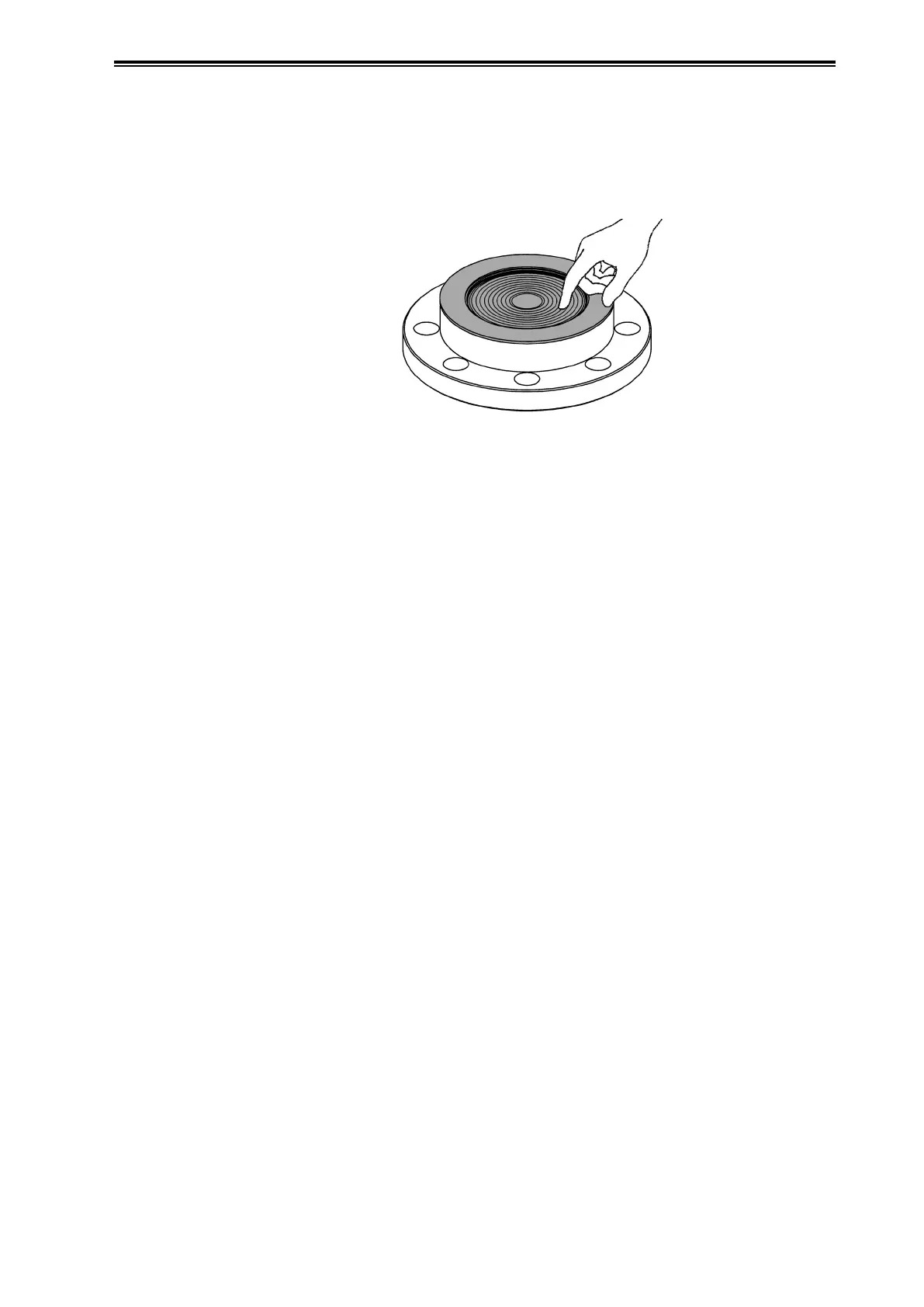
(4) Press the film outward from the center of the diaphragm such that the grease sticks out from
the periphery. Press slowly so no air remains between the diaphragm and the FEP protective
film. Press the grease out until there is almost none left on the surfaces around the gasket. After
pressing out 5-7 g of grease, the thickness of the grease on the diaphragm surface will be about
0.5 mm. When doing this, be careful notto apply excessive force that would cause deformation.
Figure 2-12. Removal of Excess Grease
(5) Place the gasket against the flange of the pressure-receiving part, and attach it to the process
flange. For information regarding the tightening torque for the bolts and nuts, see Table 2-2.
(6) If work is impeded due to zero point fluctuation, use a communicator or the like to acquire data
from before and after fastening the flange, and check that the fluctuation is on the order of
±0.1 kPa. If the fluctuation width is large, detach the pressure-receiving part from the process,
and check how the FEP protective film is attached to confirm that there are no abnormalities.
(2) 1-1/2B, 2B Flanges
When attaching the pressure-receiving part to the process side flange, follow the steps below
immediately beforehand.
(1) Hold the diaphragm surface of the pressure-receiving part of the transmitter such that it faces
upward.
(2) Apply about 10 g of Daiflon grease (about one-fourth of a tube) to the diaphragm
surfaceandthe surfaces around the flange gasket, and spread it evenly on the gasket
surfacewith your finger so that it reaches a thickness of about 0.5 mm (Figure 2-13).
Also be careful of the following during attachment.
• When applying the grease, do not apply excessive force that might deform the
diaphragm.
• Make sure that no air (bubbles) are left in the grease.
(3) Fit the FEP protective film onto the diaphragm surface. When doing this, lift one side
and fit the film gently from the opposite side so that no air remains. (See Figure 2-14.)
Also be careful of the following during attachment.
• Make the FEP protective film fit closely onto the metallic diaphragm.
• Make sure that the wave portion of the FEP protective film does not bulge out.
(4) After attachment, confirm that no air remains between the diaphragm and the FEP protective
film. If air remains, it may affect measurements. In this case, press the air out with your finger
outward from the center of the diaphragm (Figure 2-15).