2-42
Chapter 2 Installation of this Device
(3) Caution
For communication using SFN, HART, etc., external load resistance of at least 250 Ω is required. If
the receiver side load resistance is less than 250 Ω, insert a loop with the necessary resistance. Also,
when performing external meter wiring, remove the jumper.
(4) Pipes and Cable Glands for Wiring
Run the cable to the transmitter case as follows.
• Attach a conduit pipe or cable gland to conduits for electrical wiring for the device. Follow these
instructions when performing wiring.
• In order to prevent rainwater from entering the device, waterproof the connectors using sealant
material or the like. In addition, select cable glands that ensure waterproofing and dustproofing.
• Use elbow pipes as necessary to change the direction of the electrical wiring.
(5) Grounding
There are grounding points on the terminal block inside the device, as well as on the outside of the
device. Ground the device using any of these.
• Ground terminals provide D class grounding (grounding resistance of 100 Ω or less).
• For explosion-proof models, grounding work is absolutely necessary.
• Precautions if there is welding work near the transmitter
Ground welding machines and welding power transformers directly; do not ground them to
the stanchion pipe to which the transmitter is attached. This device may be affected by welding
current.
• Do not allow external grounding wires to come into direct contact with the case. Insert
terminals between flat washers.
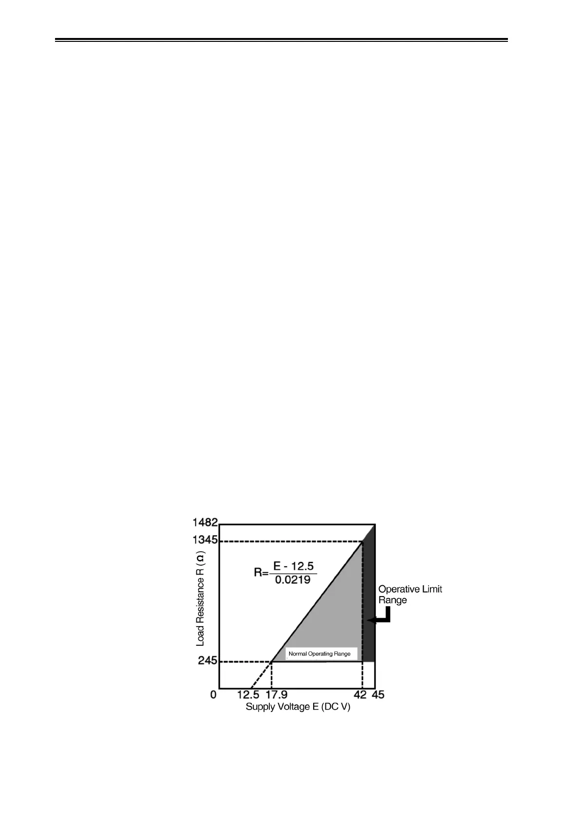
(6) Power Supply and External Load Resistance
The relationship between the power supply voltage and external load resistance used with this
device must be held within the range shown in the diagram below. External load resistance is the
total resistance connected to the output terminals of the device, such as resistance from cables
configured into a loop, and internal resistance from instruments connected at intermediate
locations.
Figure 2-47. Relationship between Supply Voltage and External Load Resistance

 Loading...