Method Action Result
Push Button
Press and hold the TEACH button for more than 2 seconds.
Light Operate:
and
flash on the display. The DYN, FGS,
and BGS indicators flash.
Dark Operate:
and
flash on the display. The DYN, FGS,
and BGS indicators flash.
Remote Input
No action required. N/A
3. Teach the sensor.
Method Action Result
Push Button
Press the TEACH button.
The switching threshold flashes rapidly
and the sensor returns to Run mode.
Remote Input
Single-pulse the remote input.
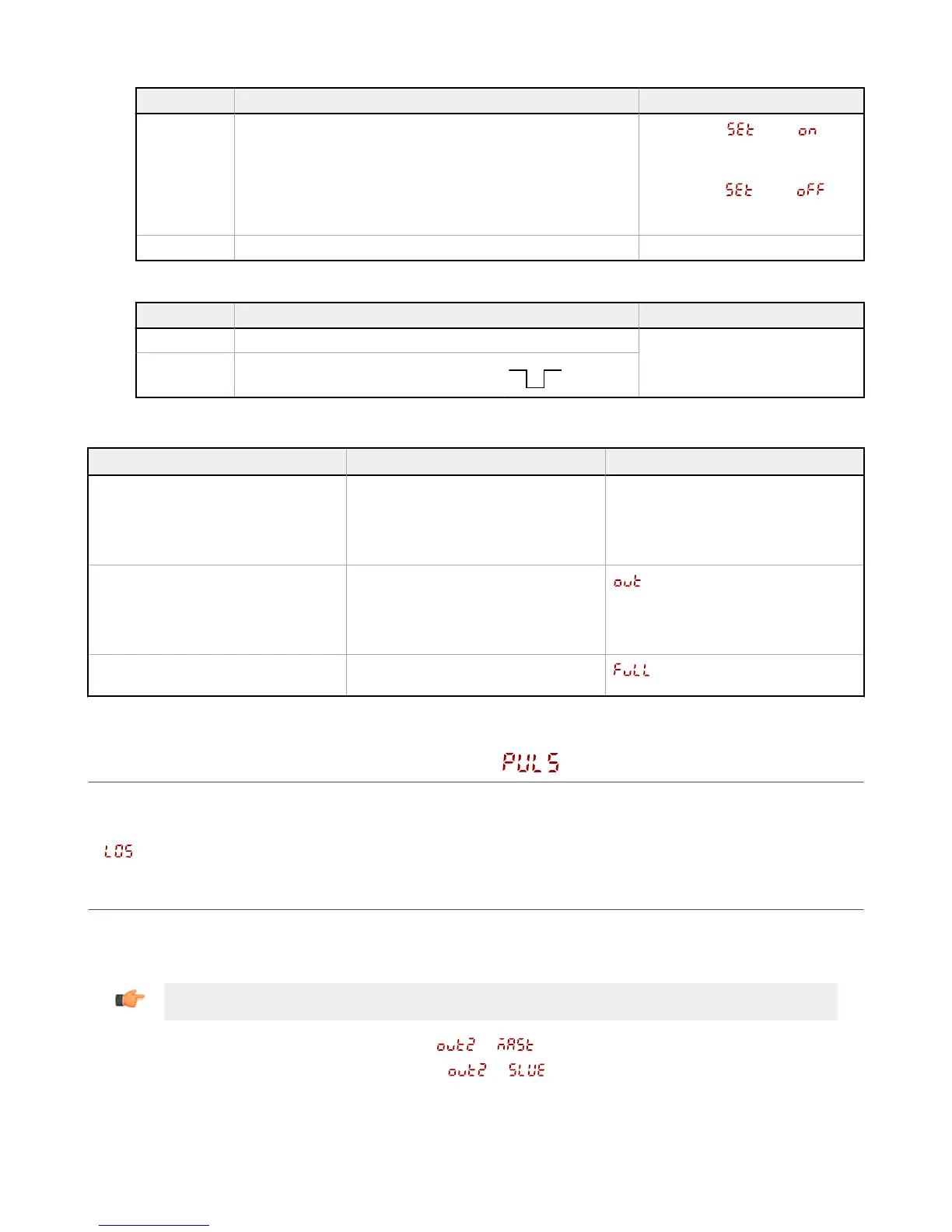
Table 7: Expected TEACH Behavior for Dual (Intensity + Distance) Mode
Condition TEACH Result Display
One valid reference surface is taught
within sensing range
Sets a dual (intensity + distance) window
centered around the taught reference
surface. The ± window size is the
previously used switching threshold, or
75% by default.
The switching threshold flashes on the
display.
One reference surface is taught outside
the sensing range
Sets a dual (intensity + distance) window
centered around the taught reference
surface that is outside the sensing range.
The sensing conditions may not be as
reliable.
flashes on the display.
One invalid TEACH Point No reference surface is taught, the output
will change when any object is detected.
flashes on the display.
3.7 Pulse Frequency Modulation (PFM) Output
The Q4X can generate pulses whose frequency are proportional to the sensor's measured distance, thereby providing a method for
representing an analog signal with only a discrete counter. The sensing range of the sensor is scaled from 100 to 600 Hz (100 Hz
equals the near range limit of the sensor, 600 Hz equals the far sensing range limit). An output of 50 Hz represents a Loss of Signal
(
) condition where there is no target or the target is out of the sensor's range.
3.8 Sync Master/Slave
Two Q4X sensors may be used together in a single sensing application. To eliminate crosstalk between the two sensors, configure
one sensor to be the master and one to be the slave. In this mode, the sensors alternate taking measurements and the response
speed doubles.
Important: The master sensor and the slave sensor must be programmed for the same Response Speed and Gain and
Sensitivity settings. The master sensor and slave sensor must share a common power source.
1. Configure
the first sensor as the master; navigate:
> .
2. Configure
the second sensor as the slave; navigate:
> .
3.
Connect the gray (input) wires of the two sensors together.
Q4X Stainless Steel Laser Sensor with Dual Discrete Outputs and IO-Link
28 www.bannerengineering.com - Tel: 763.544.3164