3. Check the sensor alignment.
4.
Tighten the mounting screws to secure the sensor (or the sensor and the bracket) in the aligned position.
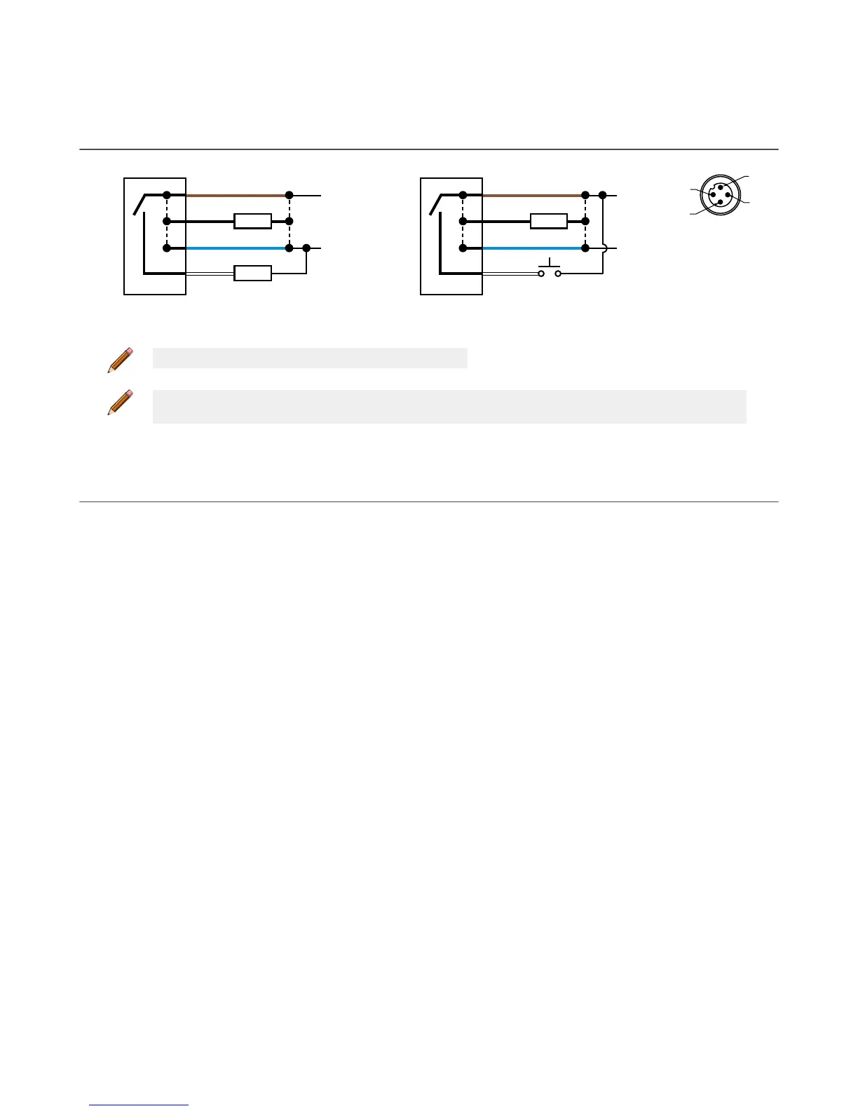
2.4 Wiring Diagram
4
1
3
2
10-30V dc
CH1
CH2
+
–
PUSH-PULL
Load
Load
Figure 10. Channel 2 as PNP discrete or PFM output
4
1
3
2
10-30V dc
CH1
CH2
+
–
PUSH-PULL
Load
Remote
Input
Figure 11. Channel 2 as remote input
Key
1 = Brown
2 = White
3 = Blue
4 = Black
Note: Open lead wires must be connected to a terminal block.
Note: The Channel 2 wire function is user-selectable. The default for the wire is PNP output. See the Instruction Manual
for details regarding use as remote input or PFM output.
2.5 Cleaning and Maintenance
Handle the sensor with care during installation and operation. Sensor windows soiled by fingerprints, dust, water, oil, etc. may
create stray light that may degrade the peak performance of the sensor. Blow the window clear using filtered, compressed air, then
clean as necessary using water and a lint-free cloth.
Q4X Stainless Steel Laser Sensor with Dual Discrete Outputs and IO-Link
www.bannerengineering.com - Tel: 763.544.3164 7