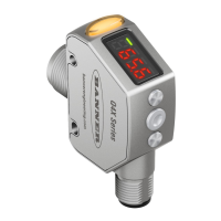
1.3 Features
Figure 2. Sensor Features
1. Output Indicator (Amber)
2.
Display
3. Buttons
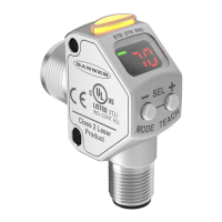
1.3.1 Display and Indicators
The display is a 4-digit, 7-segment LED. The main screen is the Run mode screen.
For 2-pt, BGS, FGS, and DYN TEACH modes, the display shows the current distance to the target in millimeters. For dual TEACH
mode, the display shows the percentage matched to the taught reference surface. A display value of
indicates the sensor
has not been taught.
Figure 3. Display in Run Mode
1. Stability Indicator (STB—Green)
2.
Active TEACH Indicators
• DYN—Dynamic (Amber)
• FGS—Foreground Suppression (Amber)
• BGS—Background Suppression (Amber)
Note: The indicators represent the currently selected channel. However, if Output 2 is set to something other than LO, DO,
or Complementary, then the indicators represent the Channel 1 status.
Output Indicator
•
On—Output is on
• Off—Output is off
Active TEACH Indicators (DYN, FGS, and BGS)
• DYN, FGS, and BGS all off—Two-point TEACH mode
selected (default)
• DYN on—Dynamic TEACH mode selected
• FGS on—Foreground suppression TEACH mode
selected
• BGS on—Background suppression TEACH mode
selected
• DYN, FGS, and BGS all on—Dual TEACH mode
selected
Stability Indicator (STB)
•
On—Stable signal within the specified sensing range
•
Flashing—Marginal signal, the target is outside the
limits of the specified sensing range, or a multiple peak
condition exists
•
Off—No target detected within the specified sensing
range
1.3.2 Buttons
Use the sensor buttons (SELECT)(TEACH), (+)(CH1/CH2), and (-)(MODE) to program the sensor.
Q4X Stainless Steel Laser Sensor with Dual Discrete Outputs and IO-Link
4 www.bannerengineering.com - Tel: 763.544.3164