4. Lamp & lamp house
11
Image 4-18
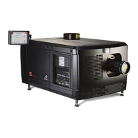
5. Install the UV bloc ker assembly as illustrated. Use the opening at the side of the Lamp House to guide the anode pin of the
xenon lamp into the anode s upporting mec hanism of the UV blocker. Make sure that the tick wire of the lamp anode is oriented
to the right.
Image 4-19
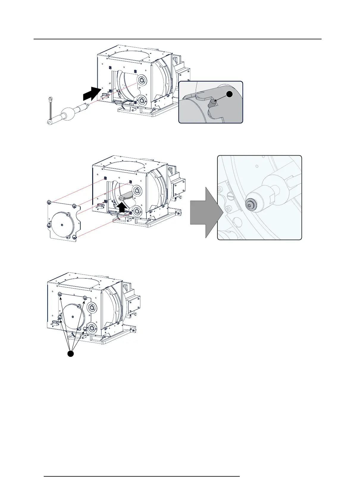
6. Secure the UV bloc ker by fastening the four quarter turn screws (reference 2) a s illustrated.
Note: Ensure that the quarter turn screws turning wires are flus h with t he cover o r interference will occur while inserting the
Lamp House into the projector.
2
Image 4-20
7. Install the anode wire lug (reference 3) upon the anode socket inside the Lamp House as illustrated. Use an open-end wrench
of 2 2 mm to hold the first nut (reference 4) while fastening the s econd nut (reference 5) w ith a torque of 25 N m (1 8,4 lbf*ft) using
a torque wrench. Ensure that there is a flat washer (reference 6 & 7) at both sides of the wire lug (reference 3).
Warning: A torque of 25 Nm (18,4 lbf*ft) must be ap plied to fasten the nuts. Make sure that there is no tension on the a node
wire of the x enon lamp.
Note: Alter tightening the two nuts, the connector should still be “floating”.
42
R59770491 DP2K-32B 30/04/2010