12. Lamp House & Lamp replacement
11
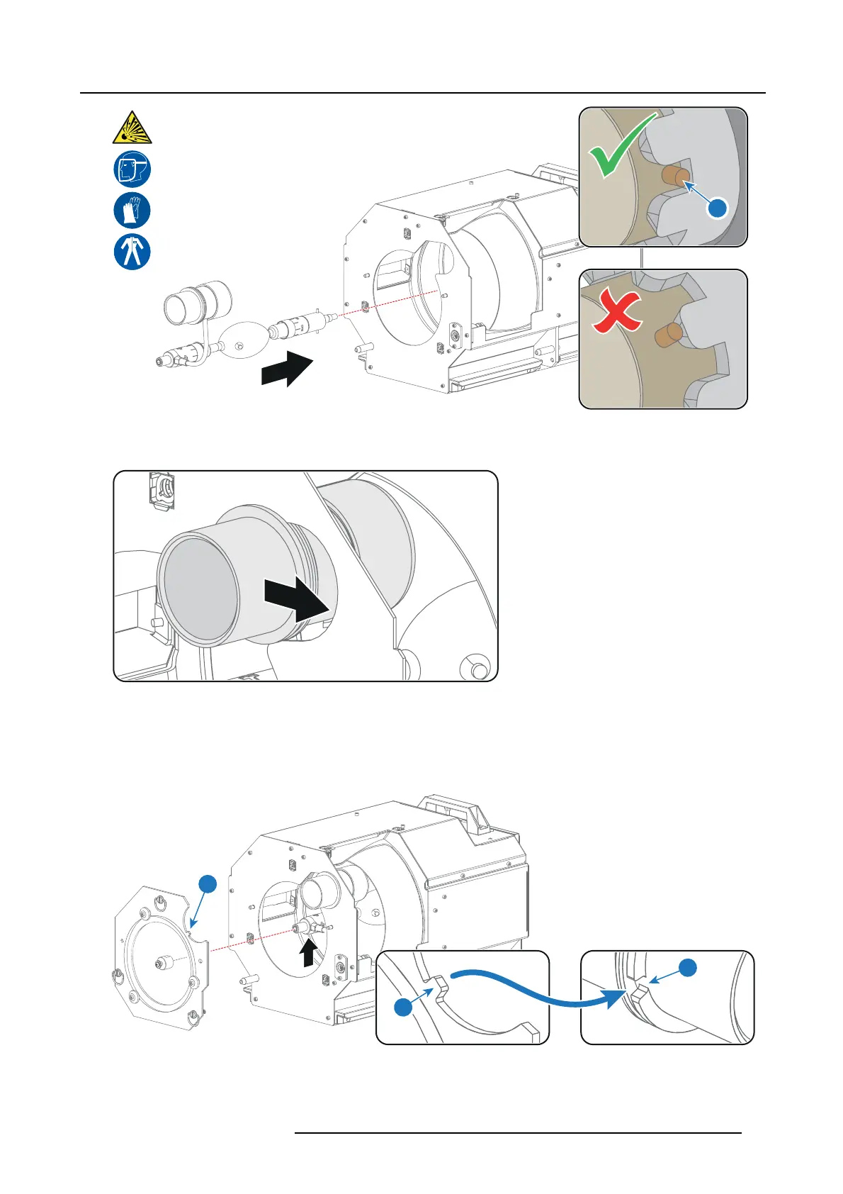
Image 12-28
6. S lide the ano de co nnector into position on the Lam p H ouse as illustrated.
Caution: Avoid any tension on the anode wire, ensuring there is no mechani
cal stress on the lam p.
Image 12-29
7. Install the UV blocker assembly as illustrated. W hile supporting the lamp, via the Lamp House s ide opening, guide the UV blocker
(with supporting mechanism) into position and eng age it with the lamp.
Install the UV blocker assembly as illustrated. Use the opening at the side of the Lamp Hous e to guide the anode pin of the
xenon lamp into the anode supporting mechanism of the UV bloc ker.
Note: Make sure that the notch (reference 12 of image 12-30) of the UV blocker assembly matches with the gap (reference 12
of image 12-30) of the anode connector.
12
12
13
Image 12-30
8. Secur e the UV blocker by fastening the three quarter turn screws (reference 5 image 12-31) as illustrated.
R5977692 DP2K-S SERIES 10/12/2012
91

 Loading...


