PDS • User’s Guide 13
2. Hardware Orientation
PDS Rear Panel
map=oÉ~ê=m~åÉä
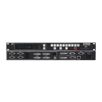
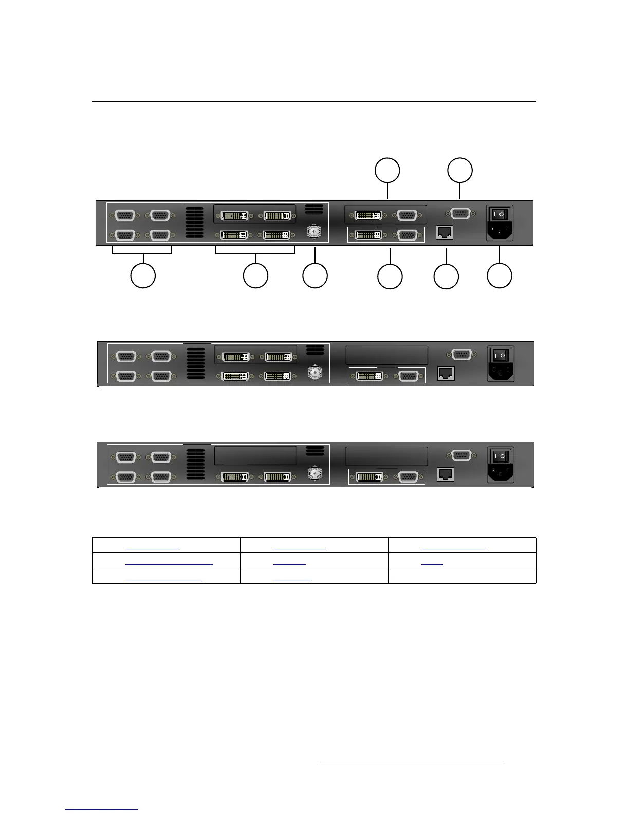
The figures below illustrate the rear panels for PDS-902, PDS-901, and PDS-701:
Figure 2-1. PDS-902 Rear Panel
Figure 2-1. PDS-901 Rear Panel
Figure 2-1. PDS-701 Rear Panel
Following are descriptions of each rear panel connector:
1) Analog Inputs
Four HD-15 connectors are provided for the system’s Analog inputs. Please
note:
~ Each input provides 10-bits/color sampling at a maximum 150 MHz.
~ Each input supports 1:1 sampling up to 1920x1080@60 Hz. Sources
with native pixel rates greater than 150 MHz will be filtered and
undersampled at 150 Mhz. These include:
• 1600x1200@60 (162.0MHz)
• 1920x1080p@60 (173.0 MHz)
Input 1
Input 3
Input 2
Input 4
Input 5 Input 6
SDI
PROGRAM
VIDEO INPUTS
ETHERNET
Input 8
SERIAL
Preview
Input 7 Input 8
Input 1
Input 3
Input 2
Input 4
Input 5 Input 6
SDI
PROGRAM
VIDEO INPUTS
ETHERNET
Input 8
SERIAL
Input 7 Input 8
Input 1
Input 3
Input 2
Input 4
Input 5 Input 6
SDI
PROGRAM
VIDEO INPUTS
ETHERNET
Input 8
SERIAL
1) Analog Inputs 4) Main Outputs 7) Preview Outputs
2) DVI and Analog Inputs 5) Ethernet 8) Serial
3) 3G/HD/SD SDI Input 6) AC Power