Image Data Formats & Structures
5-12 BASLER A102
f
DRAFT
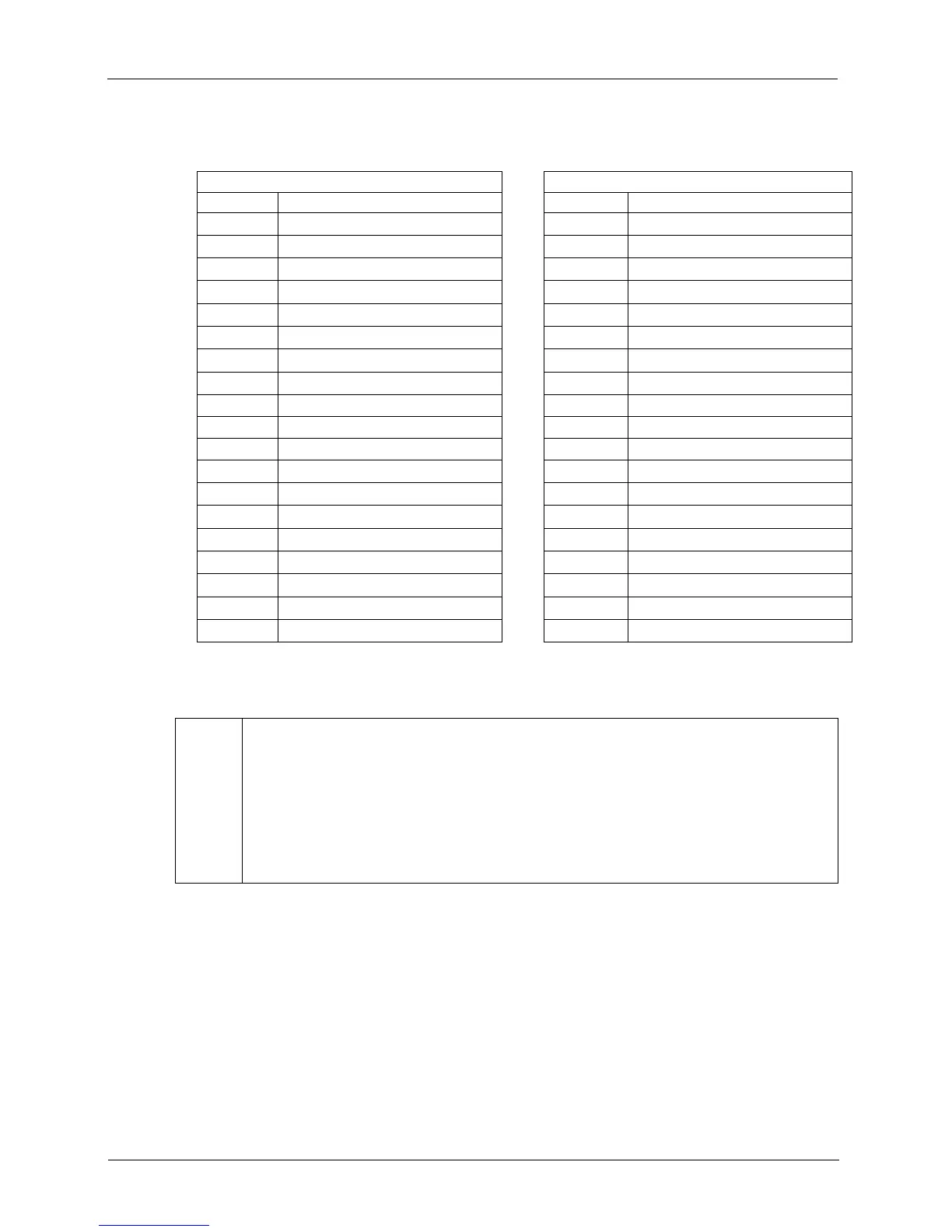
For Filter ID = 3 (BG / GR)
Even Lines Odd Lines
Byte Data Byte Data
B
0
Low byte of blue value for P
0
B
0
Low byte of green value for P
0
B
1
High byte of blue value for P
0
B
1
High byte of green value for P
0
B
2
Low byte of green value for P
1
B
2
Low byte of red value for P
1
B
3
High byte of green value for P
1
B
3
High byte of red value for P
1
B
4
Low byte of blue value for P
2
B
4
Low byte of green value for P
2
B
5
High byte of blue value for P
2
B
5
High byte of green value for P
2
B
6
Low byte of green value for P
3
B
6
Low byte of red value for P
3
B
7
High byte of green value for P
3
B
7
High byte of red value for P
3
• • • •
• • • •
• • • •
B
m-7
Low byte of blue value for P
n-3
B
m-7
Low byte of green value for P
n-3
B
m-6
High byte of blue value for P
n-3
B
m-6
High byte of green value for P
n-3
B
m-5
Low byte of green value for P
n-2
B
m-5
Low byte of red value for P
n-2
B
m-4
High byte of green value for P
n-2
B
m-4
High byte of red value for P
n-2
B
m-3
Low byte of blue value for P
n-1
B
m-3
Low byte of green value for P
n-1
B
m-2
High byte of blue value for P
n-1
B
m-2
High byte of green value for P
n-1
B
m-1
Low byte of green value for P
n
B
m-1
Low byte of red value for P
n
B
m
High byte of green value for P
n
B
m
High byte of red value for P
n
L
As shown in the tables above, when the camera is set for 16 bit output, data is placed
in the image buffer in little endian format. (The DCAM standard specifies big endian
format for 16 bit output, but we do not follow this recommendation. We use little en-
dian format so that 16 bit data can be processed more effectively on little endian hard-
ware such as Intel
®
processor based PCs.)
When the camera is set for 16 bit output, 16 bits of data will be transmitted for each
pixel but only 12 bits are effective (see Section 3.9).