Image Data Formats & Structures
BASLER A102
f 5-9
DRAFT
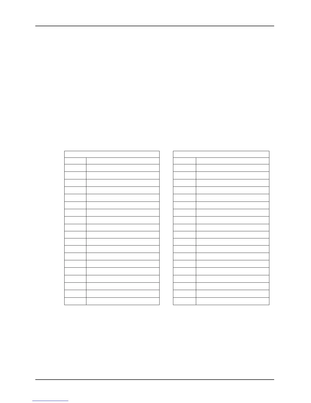
5.3.5 Data Format with the Camera Set for Raw 16 Output
The tables below describe how the data for the odd lines and for the even lines of a received frame
will be ordered in the image buffer in your PC.
The following standards are used in the tables:
P
0
= the first pixel transmitted by the camera for a line
P
n
= the last pixel transmitted by the camera a line
B
0
= the first byte of data for a line
B
m
= the last byte of data for a line
For Filter ID = 0 (RG / GB)
Even Lines Odd Lines
Byte Data Byte Data
B
0
Low byte of red value for P
0
B
0
Low byte of green value for P
0
B
1
High byte of red value for P
0
B
1
High byte of green value for P
0
B
2
Low byte of green value for P
1
B
2
Low byte of blue value for P
1
B
3
High byte of green value for P
1
B
3
High byte of blue value for P
1
B
4
Low byte of red value for P
2
B
4
Low byte of green value for P
2
B
5
High byte of red value for P
2
B
5
High byte of green value for P
2
B
6
Low byte of green value for P
3
B
6
Low byte of blue value for P
3
B
7
High byte of green value for P
3
B
7
High byte of blue value for P
3
• • • •
• • • •
• • • •
B
m-7
Low byte of red value for P
n-3
B
m-7
Low byte of green value for P
n-3
B
m-6
High byte of red value for P
n-3
B
m-6
High byte of green value for P
n-3
B
m-5
Low byte of green value for P
n-2
B
m-5
Low byte of blue value for P
n-2
B
m-4
High byte of green value for P
n-2
B
m-4
High byte of blue value for P
n-2
B
m-3
Low byte of red value for P
n-1
B
m-3
Low byte of green value for P
n-1
B
m-2
High byte of red value for P
n-1
B
m-2
High byte of green value for P
n-1
B
m-1
Low byte of green value for P
n
B
m-1
Low byte of blue value for P
n
B
m
High byte of green value for P
n
B
m
High byte of blue value for P
n