Basic Operation & Standard Features
3-16 BASLER A102
f
DRAFT
3.5 Gain and Brightness
The major components in the A102f electronics include:
a CCD sensor, one VGC (Variable Gain Control), and
one ADC (Analog to Digital Converter). The pixels in
the CCD sensor output voltage signals when they are
exposed to light. These voltages are amplified by the
VGC and transferred to the ADC which converts the
voltages to digital output signals.
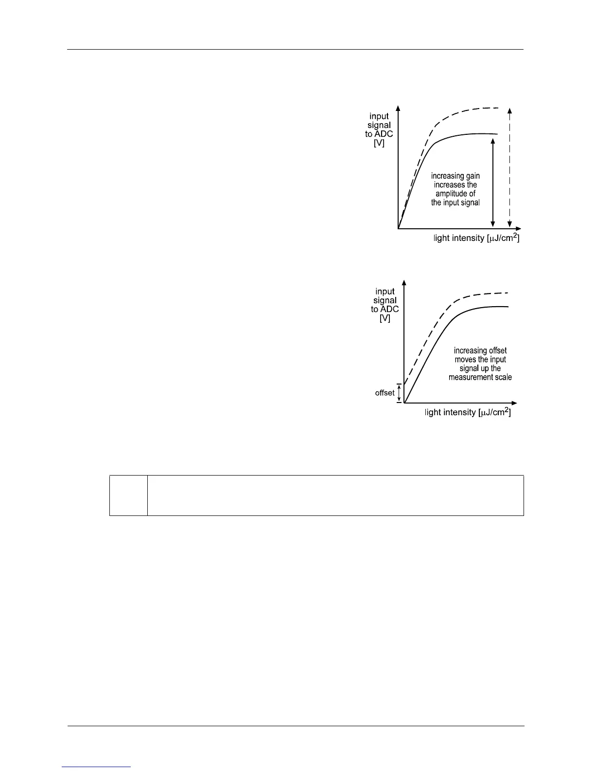
Two parameters, gain and offset are associated with
the VGC. As shown in Figures 3-7 and 3-8, increasing
or decreasing the gain increases or decreases the
amplitude of the signal that is input to the ADC.
Increasing or decreasing the offset moves the signal up
or down the measurement scale but does not change
the signal amplitude.
For most applications, black should have a gray value
of 1 and white should have a gray value of 255 (in
modes that output 8 bits per pixel) or 4095 (in modes
that output 12 effective bits per pixel). Attempt to
achieve this by varying exposure and illumination
rather than changing the camera’s gain. The default
gain is the optimal operating point (minimum noise) and
should be used if possible.
L
Because increasing gain increases both signal and noise, the signal to noise ratio
does not change significantly when gain is increased.