Camera Interface
BASLER A102
f 2-7
DRAFT
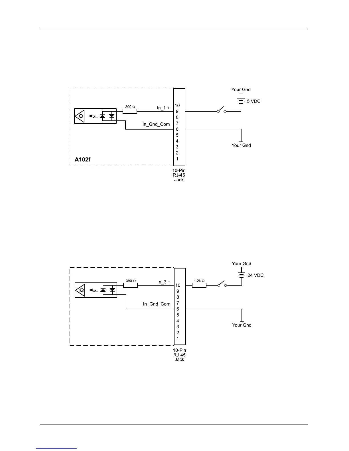
2.5.3 Typical Input Circuits
Figure 2-4 shows a typical 5 VDC circuit you can use to input a signal into the camera. In Figure
2-4, the signal is applied to input port 1.
Figure 2-4: Typical 5 VDC Input Circuit
Figure 2-5 shows a typical 24 VDC circuit you can use to input a signal into the camera. Notice
that an external 1.2 k resistor has been added to the circuit. This will result in approximately 15
mA being applied to the input. In Figure 2-5, the signal is applied to input port 3.
Figure 2-5: Typical 24 VDC Input Circuit