EasyManuals Logo

Basler Camera User Manual

Basler Camera
272 pages
To Next Page IconTo Next Page
To Previous Page IconTo Previous Page
Page #61 background imageLoading...
Page #61 background image
AW00123402000 Physical Interface
Basler ace USB 3.0 51
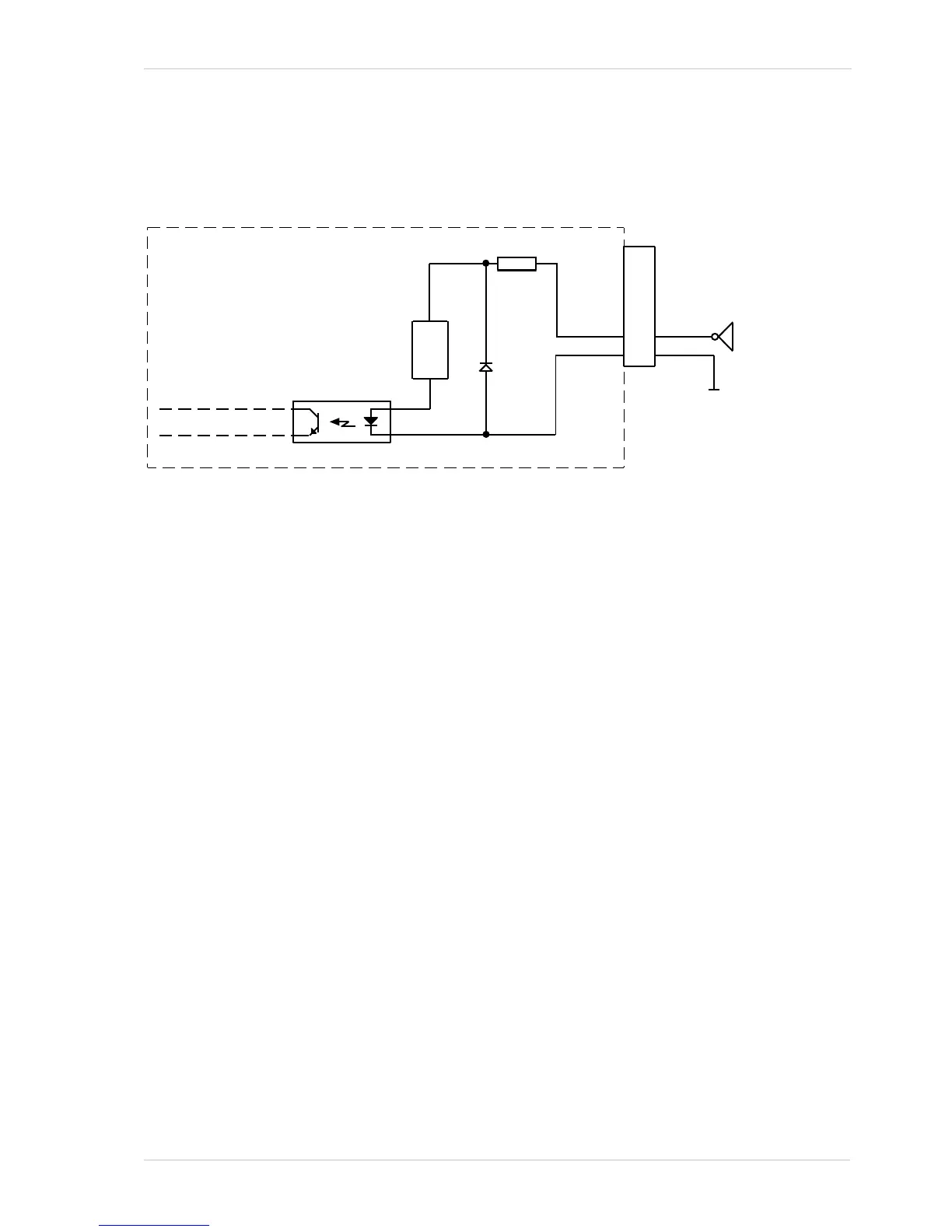
Figure 31 shows a schematic for the opto-isolated input line. The absolute maximum input supply
voltage is +30.0 VDC. The current draw for the input line is between 5 mA and 15 mA.
As an example, the use of a TTL or CMOS logic gate in the external circuit is shown.
For more information about input line pin assignments and pin numbering, see Section 5.2 on
page 46.
For more information about how to use an externally generated frame start trigger (ExFSTrig) signal
to control acquisition start, see Section 6.4 on page 99.
For more information about configuring the input line, see Section 5.11 on page 65.
Your
Gnd
6-pin
Receptacle
1
6
3
4
2
5
Camera
10
Ω
Logic Gate
Fig. 31: Opto-isolated Input Line Schematic with a Typical External Circuit (Simplified)
Current
Limiter

Table of Contents

Questions and Answers:

Question and Answer IconNeed help?

Do you have a question about the Basler Camera and is the answer not in the manual?

Basler Camera Specifications

General IconGeneral
CategorySecurity Camera
BrandBasler
ResolutionVaries by model
Sensor TypeCMOS
Frame RateVaries by model
DimensionsVaries by model
WeightVaries by model
InterfaceGigE, USB 3.0
Lens MountC-Mount, CS-Mount

Related product manuals