AW00123402000 Physical Interface
Basler ace USB 3.0 63
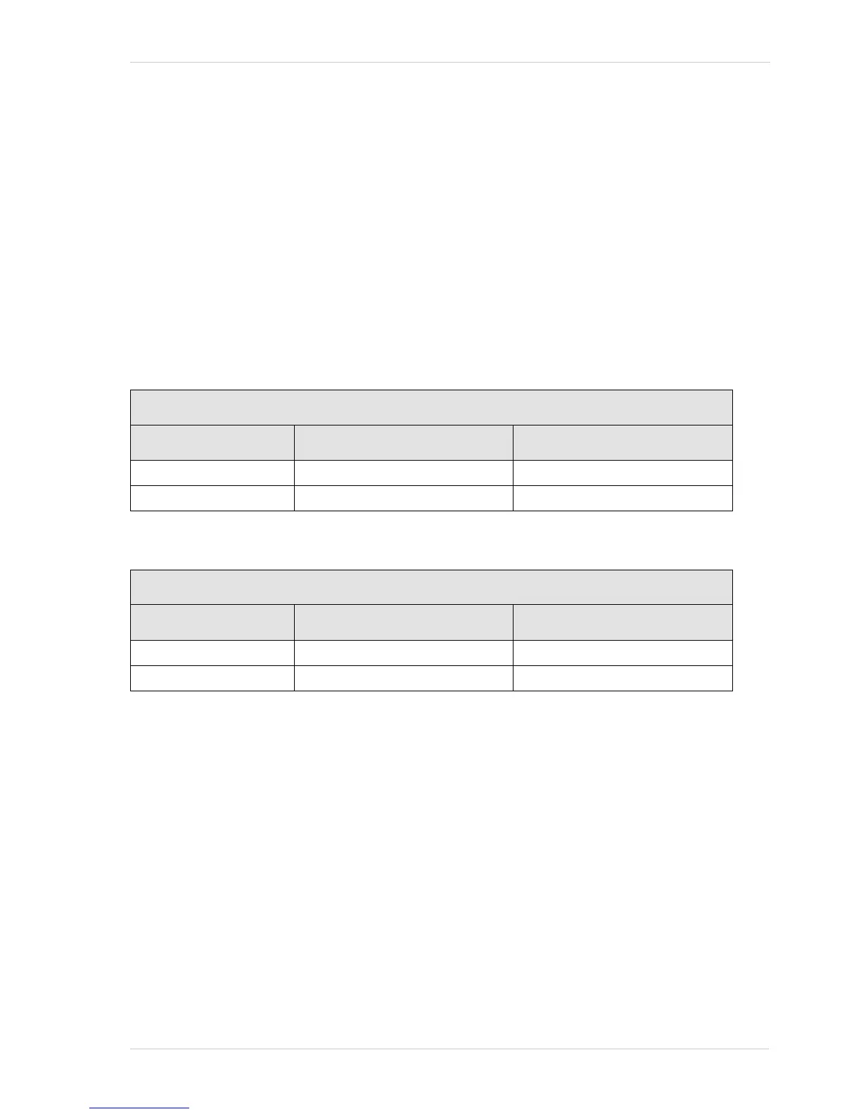
5.10.3 Measured Propagation Delays
The propagation delays reported in this section (see Tab le 13 and Table 14) are likely to be near-
minimum values related to "slow" edges.
The values relate to the specific camera operating conditions listed below and are based on a
camera production lot of 2000 cameras. No inferences can be drawn on propagation delays
resulting from different operating conditions.
The measured propagation delays apply only to the following operating conditions:
Housing temperature: +25 °C.
Load resistance: R
L
= 170 Ω
I/O supply voltage: U
S
= 5 VDC
For the graphical illustration of propagation delays, see Figure 37 and Figure 38.
Propagation Delays for Inputs
Fast Edge Slow Edge
Opto-isolated input 4.5 - 7.5 µs (rising edge) 19 - 28 µs (falling edge)
Direct-coupled GPIO IN < 0.5 µs (falling edge) < 1 µs (rising edge)
Table 13: Propagation Delays for the Camera Inputs (+25 °C, R
L
= 170 Ω, U
S
= 5 VDC)
Propagation Delays for Outputs
Fast Edge Slow Edge
Opto-isolated output 3 - 6 µs (falling edge) 27 - 38 µs (rising edge)
Direct-coupled GPIO OUT < 0.5 µs (falling edge) < 2.5 µs (rising edge)
Table 14: Propagation Delays for the Camera Outputs (+25 °C, R
L
= 170 Ω, U
S
= 5 VDC,
Transition Threshold = 2.0 V)