AW00123402000 Camera Functional Description
Basler ace USB 3.0 43
4.2 Overview (acA1920-25, acA2000-165,
acA2040-90, acA2500-14, acA3800-14,
acA4600-10)
The camera provides features such as an electronic rolling shutter (acA1920-25, acA2500-14,
acA3800-14, acA4600-10) or a global shutter (acA2000-165, acA2040-90) and electronic exposure
time control.
Exposure start and exposure time can be controlled by parameters transmitted to the camera via
the Basler pylon API and the USB 3.0 interface. There are also parameters available to set the
camera for single frame acquisition or continuous frame acquisition.
Exposure start can also be controlled via an externally generated "frame start trigger" (ExFSTrig)
signal applied to an input line. The ExFSTrig signal facilitates periodic or non-periodic frame
acquisition start.
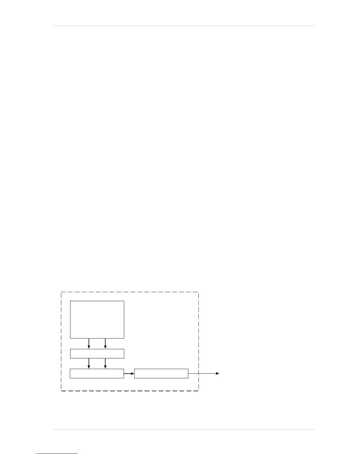
During exposure, electrical charges accumulate in the sensor’s pixels. After exposure was ended,
the accumulated charges are read out of the sensor. At readout, the charges are transported from
the row’s light-sensitive elements (pixels) to the analog processing controls (see Figure 27 on
page 43). As the charges move through the analog controls, they are converted to voltages
proportional to the size of each charge. Each voltage is then amplified by a Variable Gain Control
(VGC). Next the voltages are digitized by an Analog-to-Digital converter (ADC). After the voltages
have been amplified and digitized, they are passed through the sensor’s digital controls for
additional signal processing. The digitized pixel data leaves the sensor, passes through an FPGA,
and moves into a buffer.
The pixel data leaves the buffer and passes back through the FPGA to a controller where it is
assembled into data packets. The packets are then transmitted by bulk transfer via a USB 3
compliant cable to a USB 3 host adapter of the host PC. The controller also handles transmission
and receipt of control data such as changes to the camera’s parameters.