EasyManuals Logo

Basler Camera User Manual

Basler Camera
272 pages
To Next Page IconTo Next Page
To Previous Page IconTo Previous Page
Page #63 background imageLoading...
Page #63 background image
AW00123402000 Physical Interface
Basler ace USB 3.0 53
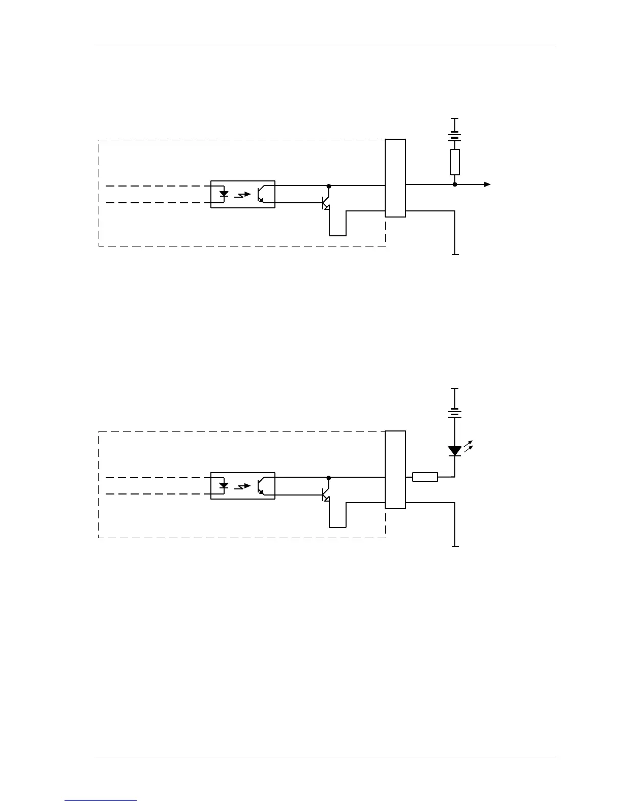
Figure 32 shows a schematic for the opto-isolated output line.
.
Figure 33 shows a typical circuit you can use to monitor the output line with an LED or an
optocoupler. In this example, the voltage for the external circuit is +24 VDC. Current in the circuit
is limited by an external resistor.
For more information about output line pin assignments and pin numbering, see Section 5.2 on
page 46.
For more information about the Exposure Active signal, see Figure 6.8.1 on page 127.
Your
Gnd
Your
Gnd
+3.3 to +24
VDC
Camera
Voltage
Output
Signal
to You
Q1
1
6
3
4
2
5
Fig. 32: Opto-isolated Output Line Schematic with a Typical Voltage Output Circuit (Simplified)
Your
Gnd
Camera
Q1
1
6
3
4
2
5
Your Gnd
LED
Output
to You
+24
VDC
2.2k
Fig. 33: Opto-isolated Output Line Schematic with a Typical LED Output Signal at +24 VDC for the External Circuit
(Simplified)

Table of Contents

Questions and Answers:

Question and Answer IconNeed help?

Do you have a question about the Basler Camera and is the answer not in the manual?

Basler Camera Specifications

General IconGeneral
CategorySecurity Camera
BrandBasler
ResolutionVaries by model
Sensor TypeCMOS
Frame RateVaries by model
DimensionsVaries by model
WeightVaries by model
InterfaceGigE, USB 3.0
Lens MountC-Mount, CS-Mount

Related product manuals