Physical Interface AW00123402000
58 Basler ace USB 3.0
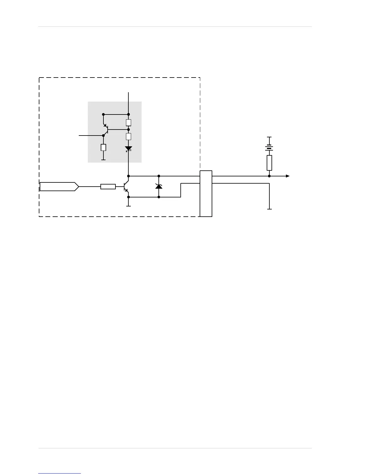
As shown in Figure 36, shows the applicable electrical circuit when a GPIO line is set to operate as
an output. The figure is drawn to specifically apply to pin 1 (Line 3) as an example but, with the
necessary modifications, it equally applies to pin 3 (Line 4).
For more information about GPIO pin assignments and pin numbering, see Section 5.2.1 on
page 46.
For more information about setting the GPIO line operation, see Section 5.11 on page 65 and
Section 5.12 on page 69.
Fig. 36: Direct-coupled GPIO Line Schematic with the GPIO Line Set as an Output and with a Typical Voltage
Output Circuit (Illustration for Pin 1 as an Example; Simplified)