Physical Interface AW00123402000
80 Basler ace USB 3.0
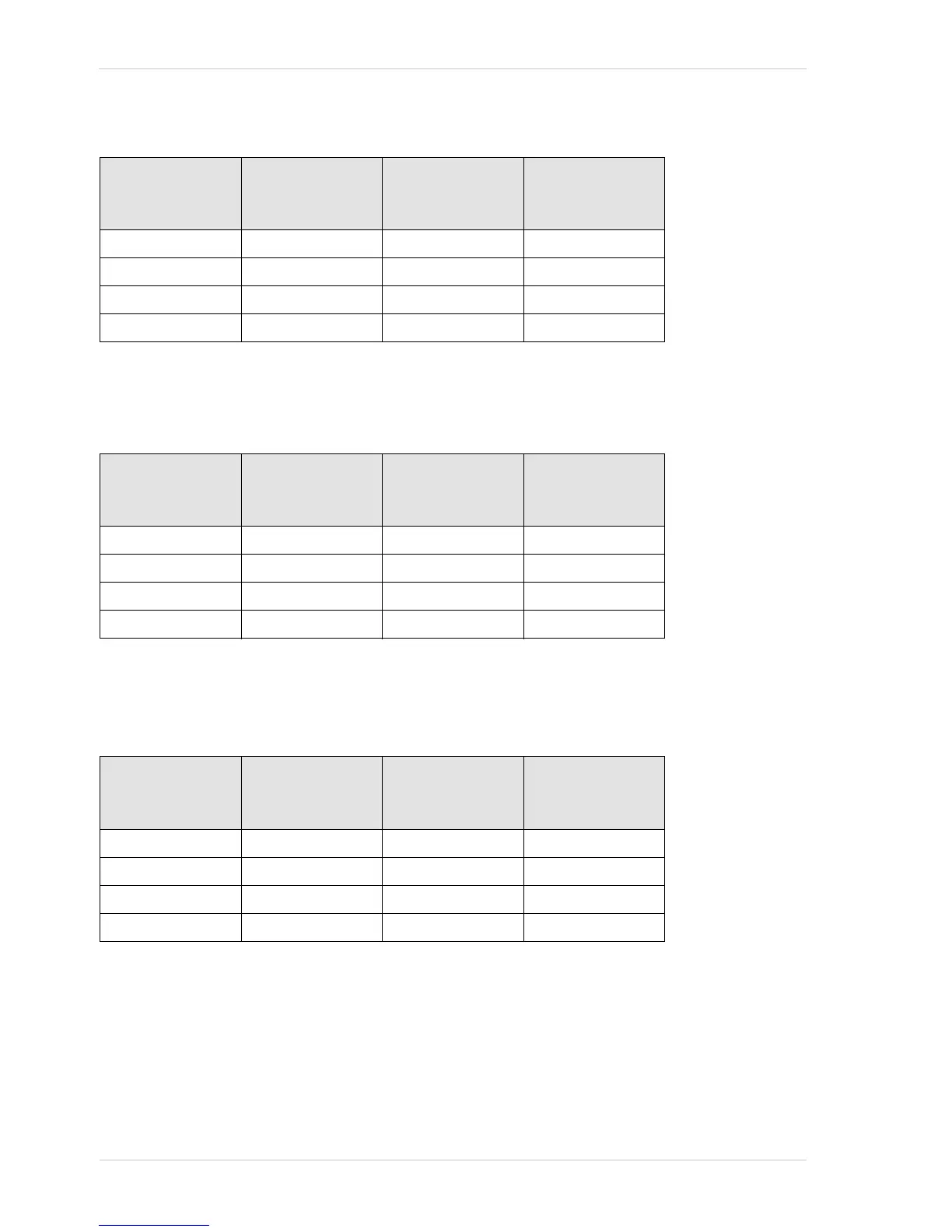
No electrical signal applied and line inverters enabled:
Electrical signals applied and line inverters disabled:
Electrical signals applied and line inverters enabled:
I/O Line Electrical Signal /
Electrical Signal
Level
LineStatus
Parameter Value
Binary Expression
of the Line Status
Parameter Value
Line 1 (input) Off/Low True 1
Line 2 (output) Off/Low False 0
Line 3 (input/output) Off/Low False 0
Line 4 (input/output) Off/Low False 0
Table 17: I/O Lines and Line Status With no Electrical Signals Applied and All Line Inverters Enabled
I/O Line Electrical Signal /
Electrical Signal
Level
LineStatus
Parameter Value
Binary Expression
of the Line Status
Parameter Value
Line 1 (input) On/High True 1
Line 2 (output) On/High False 0
Line 3 (input/output) On/High False 0
Line 4 (input/output) On/High False 0
Table 18: I/O Lines and Line Status With Electrical Signals Being Applied and All Line Inverters Disabled
I/O Line Electrical Signal /
Electrical Signal
Level
LineStatus
Parameter Value
Binary Expression
of the Line Status
Parameter Value
Line 1 (input) On/High False 0
Line 2 (output) On/High True 1
Line 3 (input/output) On/High True 1
Line 4 (input/output) On/High True 1
Table 19: I/O Lines and Line Status When Electrical Signals Are Applied With All Line Inverters Enabled