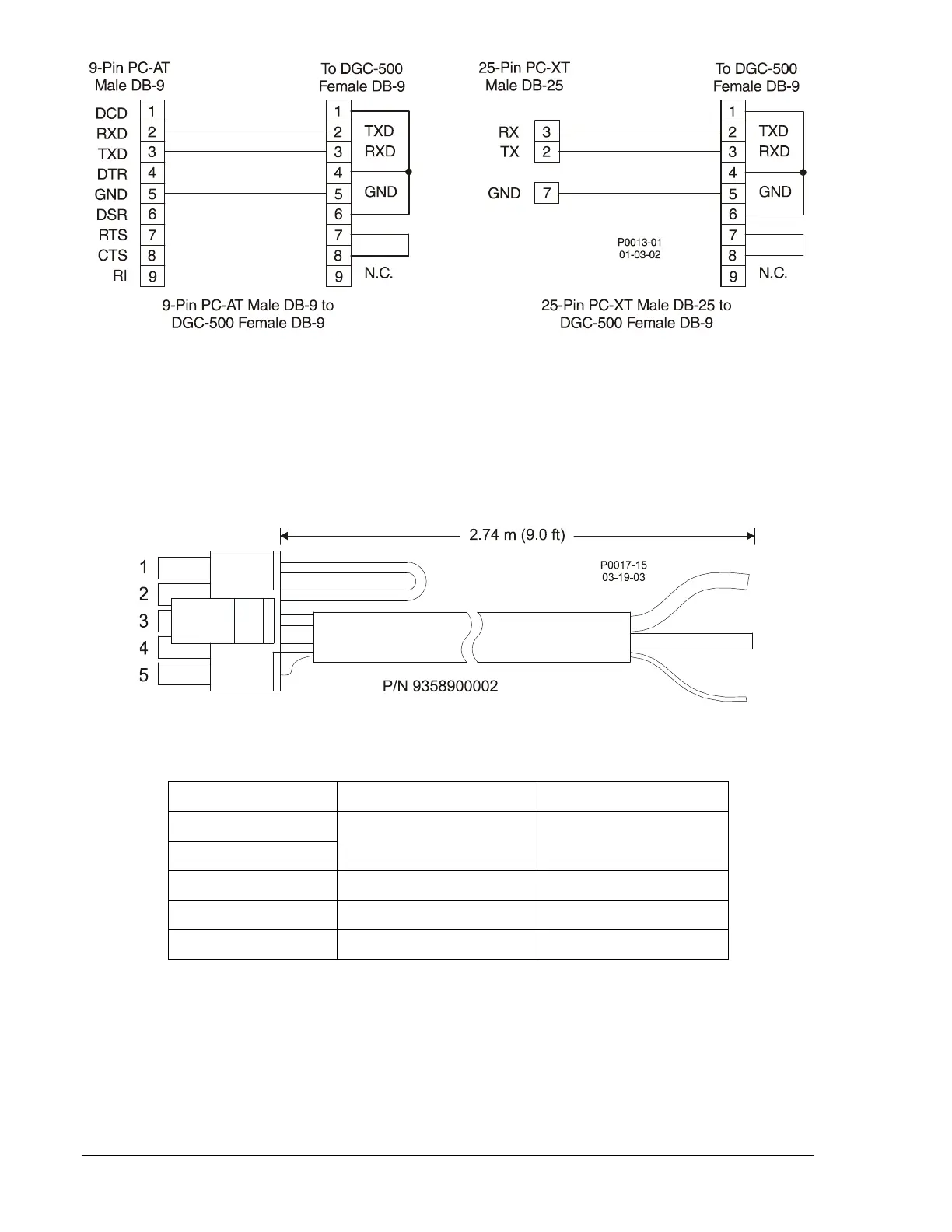
Figure 5-4. Personal Computer to DGC-500 Connections
CAN Connections
The CAN connector (J2) on the rear panel mates with the cable assembly (Basler P/N 9358900002)
provided with the DGC-500. Only units with style numbers F1J AND F5J are supplied with the cable
assembly and have connector J2 enabled. The cable assembly is shown in Figure 5-5 and the termination
assignments are listed in Table 5-2. Figure 5-6 illustrates typical DGC-500 CAN interface connections.
Figure 5-5. CAN Cable Assembly
Table 5-2. CAN Cable Assembly Termination Assignments
J2 Terminations Function User Terminations
Pin 1
Termination Resistor
∗
Pin 2
Pin 3 CAN High Red Wire
Pin 4 CAN Low Black Wire
Pin 5 Drain
Uninsulated Wire †
∗ If the DGC-500 is not providing one end of the J1939 backbone, cut the jumper connected across pins 1
and 2 to disconnect the internal terminating resistor.
† The J1939 drain (shield) should be grounded at one point only. If grounded elsewhere, cut the drain
connection to the DGC-500.
Note: If the DGC-500 is not part of the J1939 backbone, the stub connecting the DGC-500 to the
backbone should not exceed 914 mm (3 ft) in length.
5-4 DGC-500 Installation 9355400990 Rev H