SECTION 5
INSTALLATION
GENERAL
DGC-500 Digital Genset Controllers are delivered in sturdy cartons to prevent shipping damage. Upon
receipt of a system, check the part number against the requisition and packing list for agreement. Inspect
for damage, and if there is evidence of such, immediately file a claim with the carrier and notify the Basler
Electric Regional Sales Office, your Sales Representative, or a Sales Representative at Basler Electric,
Highland, Illinois.
If the device is not installed immediately, store it in the original shipping package in a moisture and dust-
free environment.
HARDWARE
DGC-500 controllers are packaged for mounting in any top-mount enclosure. The front panel is resistant
to moisture, salt fog, humidity, dust, dirt, and chemical contaminants. It also inhibits insect and rodent
entrance. DGC-500 controllers are mounted using the four permanently attached 10-32 studs. The torque
applied to the mounting hardware should not exceed 30 inch-pounds (3.4 newton meters).
MOUNTING
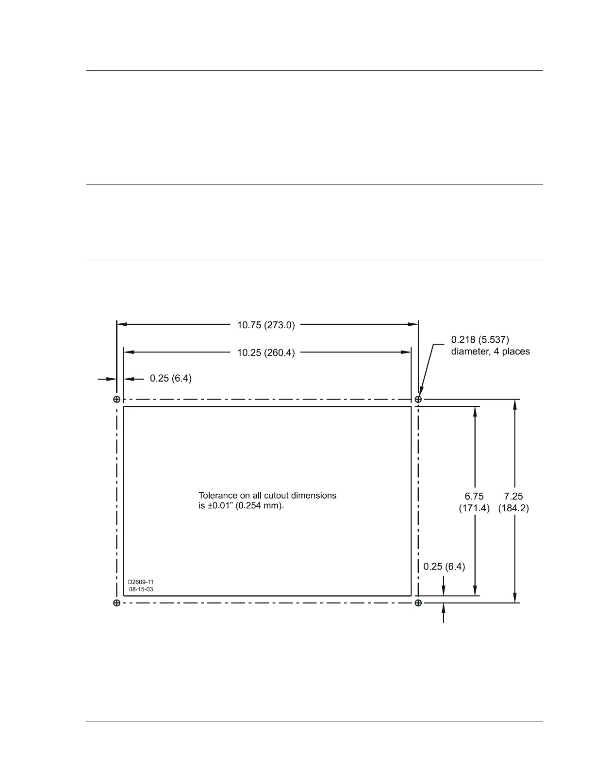
Case cutout dimensions are shown in Figure 5-1. Overall dimensions are shown in Figure 5-2. All
dimensions are shown in inches and millimeters (in parenthesis).
Figure 5-1. DGC-500 Cutout Dimensions
9355400990 Rev H DGC-500 Installation 5-1