• Cranking. Cranks the engine until it is above the crank disconnect speed.
• Resting. Occurs between crank cycles and does not crank the engine.
• Running. The unit is now running and no longer cranking.
• Cooling. Cool down running engine if a load is or was applied when going to Auto-Off mode.
• Shutting Down. ECU Only—wait for engine to stop rotating before "pulsing".
• Alarm. Alarm was triggered, wait for the alarm to clear.
State Transitions
Criteria used for deciding state transitions are based on the following input events.
• System Configuration (Run, Off, in Auto with ATS closed, in Auto with ATS open)
• Analog/ECU sender data (example: Engine Speed)
• Programmable auxiliary inputs
• Switch data (Coolant Level Switch, ATS, Emergency Stop Button)
• ECU-specific data (example clearing/requesting diagnostics)
• Various programmable timers (run-time, cycles, delays, time-out length)
• Programmable I/O settings
• Alarm settings (thresholds, enabling and timers)
• Other settings selectable through BESTCOMS.
Input events are used in deciding the following output events.
• Output relays on the DGC-500 control the generator and other devices connected to the DGC-500.
• LED output is controlled by the system configuration setting, active alarm/pre-alarms, and by the
supplying load criteria.
• The LCD is controlled by the value of data being displayed, the state of the DGC-500, and by the
viewing mode (Normal, Alternate Display, ECU Parameters, or Menu).
• The horn (or buzzer) is controlled by the Alarm Silence, Run, or Off pushbuttons, and by the Alarm
and Pre-Alarm conditions.
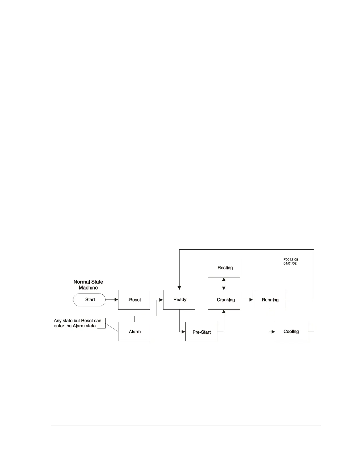
Normal Program Control
If an engine does not have an ECU, then ECU Support should be disabled so that the DGC-500 uses
analog sender data. An engine with ECU support disabled or ECU support enabled with a constant power
supply and accessible fuel solenoid will follow the normal program control flowchart of Figure 3-16.
Figure 3-16. Normal Program Control Diagram
ECU Power Support Program Control
If an engine has an ECU, then ECU support should be enabled so that the DGC-500 uses sender data
transmitted from the ECU over the J1939 interface. If the engine can be shut down only by powering off
the ECU, then the genset will need ECU power support enabled. An engine with ECU support enabled
and a need for ECU power support through the fuel solenoid will follow the ECU power support diagram
of Figure 3-17.
9355400990 Rev H DGC-500 Functional Description 3-29