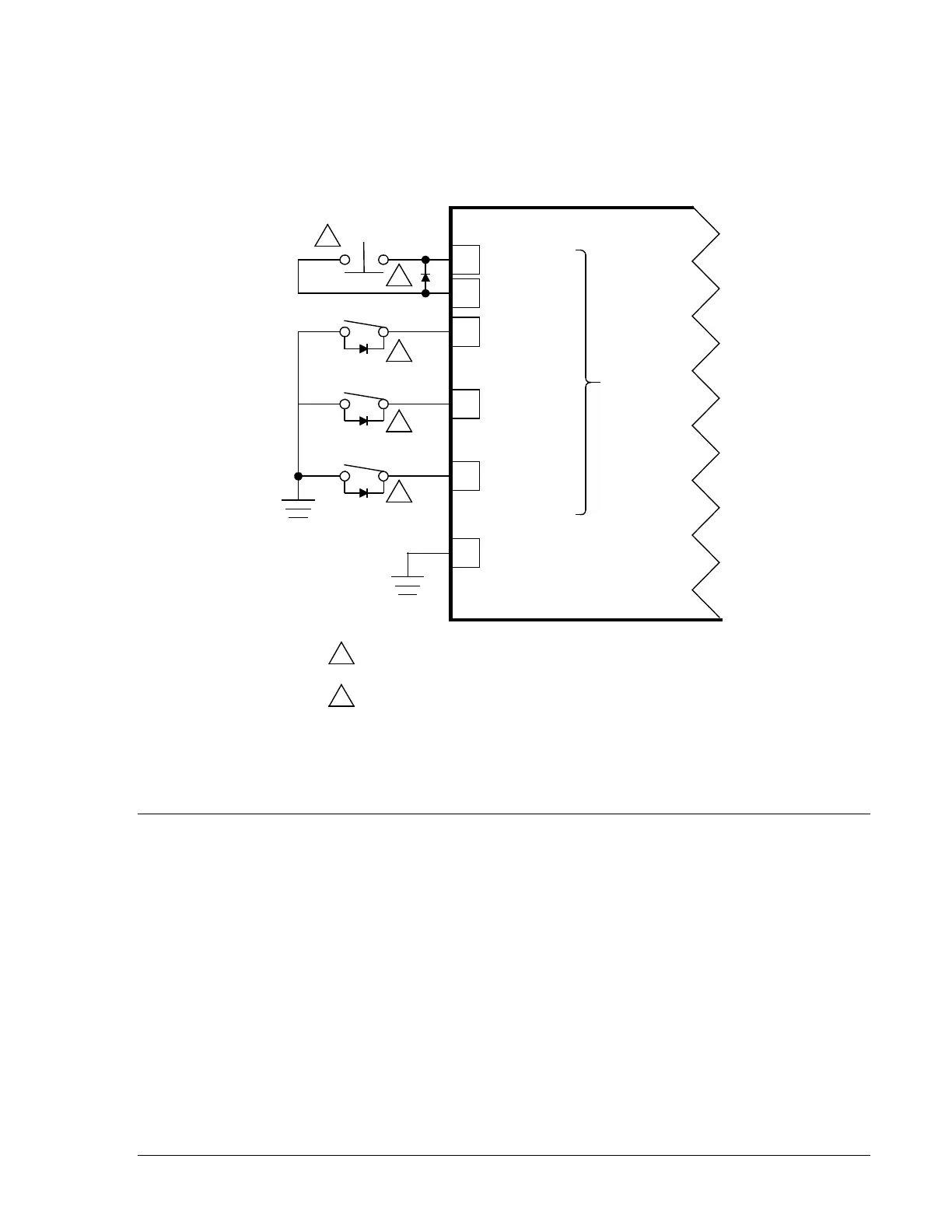
Special Contact Sensing Input Considerations
DGC-500 controllers, with version M or earlier hardware, may require additional protection for the contact
sensing inputs when used in environments with high levels of electrical noise. Additional protection can be
implemented by connecting external noise suppression diodes across the DGC-500 contact sensing
inputs. Schottky diodes, rated at 1 A, 1,000 Vdc or greater, are recommended. Figure 5-15 illustrates how
the noise suppression diodes are connected in a typical DGC-500 contact input application.
Figure 5-15. Contact Sensing Input Connections with Noise Suppression Diodes
CALIBRATION
Prior to delivery, each DGC-500 is factory calibrated and subjected to thorough testing to ensure quality,
accuracy, and performance. DGC-500 units should not require field calibration. However, the following
procedure is provided for those users desiring to perform field calibration of their DGC-500.
Equipment Required
• Single-phase 240 Vac source
• Single-phase 2 Aac source
• Resistance box, 25 - 800 ohms
P4
P3
P2
P37
P35
Emergency
Stop
Programmable
Input 2
Programmable
Input 3
Chassis
Ground
Contact
Sensing
N.C.
Input 1
Programmable
P22
1
2
2
2
2
DGC-500
P0025-06
09-02-04
Jumper terminals P35 and P37 if Emergency Stop
switch is not used.
External noise suppression diodes are rated at 1 A,
1,000 Vdc or greater.
1
2
9355400990 Rev H DGC-500 Installation 5-15