Entering Calibration Mode
Calibration is accomplished by performing the instructions called out on each of the HMI calibration menu
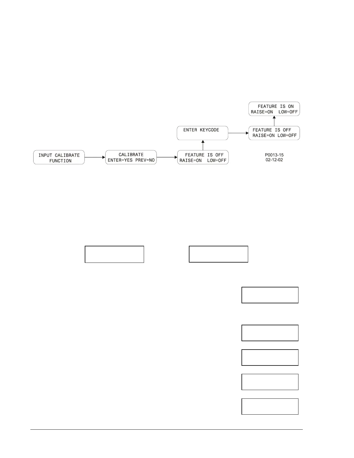
screens. The calibration menu screens reside in a branch of Menu 3: Sensing Devices. Figure 5-16
illustrates the process of entering the calibration mode and the following steps describe the process.
1. Navigate to Menu 3: Sensing Devices and scroll up or down to the screen labeled INPUT
CALIBRATE FUNCTION.
2. Perform the steps illustrated by Figure 5-16 to enable calibration (screen indicates FEATURE IS
ON). Use the Select/Enter pushbutton to move right. Use the Raise/Scroll pushbutton to move up.
Figure 5-16. Calibration Mode Navigation
Calibration Procedure
Once calibration is enabled, the following steps are performed to calibrate the DGC-500.
After each calibration step is performed, a screen indicating the success of the previous step is displayed.
Figure 5-17 shows the screens resulting from a successful calibration step and an unsuccessful
calibration step.
Successful Calibration Unsuccessful Calibration
Figure 5-17. Successful and Unsuccessful Calibration Screens
1. While viewing the FEATURE IS ON screen (illustrated in Figure 5-16),
press the Select/Enter pushbutton to begin the calibration process. The
first calibration screen (displayed at right) appears. Apply 240 Vac to the
voltage sensing inputs for phase A (terminal P23) and Neutral (terminal
P30). Press the Lower/Scroll pushbutton.
2. Press the Raise/Scroll
pushbutton. The screen at right is displayed.
Apply 240 Vac to the voltage sensing inputs for phase B (P26) and
Neutral (P30). Press the Lower/Scroll pushbutton.
3. Press the Raise/Scroll
pushbutton. The screen at right is displayed.
Apply 240 Vac to the voltage sensing inputs for phase C (P29) and
Neutral (P30). Press the Lower/Scroll pushbutton.
4. Press the Raise/Scroll
pushbutton. The screen at right is displayed.
Apply 2 Aac to the current sensing inputs for phase A (P10 and P11).
Press the Lower/Scroll pushbutton.
5. Press the Raise/Scroll
pushbutton. The screen at right is displayed.
Apply 2 Aac to the current sensing inputs for phase B (P12 and P14).
Press the Lower/Scroll pushbutton.
RAISE FOR NEXT
CAL SET/UNIT BAD
RAISE FOR NEXT
240 VAC TO A-N
PRESS LOWER KEY
240 VAC TO B-N
PRESS LOWER KEY
240 VAC TO -N
PRESS LOWER KEY
2 AAC TO A CT
PRESS LOWER KEY
2 AAC TO B CT
PRESS LOWER KEY
5-16 DGC-500 Installation 9355400990 Rev H