6. Press the Raise/Scroll
pushbutton. The screen at right is displayed.
Apply 2 Aac to the current sensing inputs for phase V (P15 and P17).
Press the Lower/Scroll pushbutton.
7. Press the Raise/Scroll
pushbutton. The screen at right is displayed.
Connect a resistance of 30 ohms across the coolant temperature sender
input (P18 and P19). Press the Lower/Scroll pushbutton.
8. Press the Raise/Scroll
pushbutton. The screen at right is displayed.
Connect a resistance of 60 ohms across the coolant temperature sender
input (P18 and P19). Press the Lower/Scroll pushbutton.
9. Press the Raise/Scroll
pushbutton. The screen at right is displayed.
Connect a resistance of 100 ohms across the coolant temperature sender
input (P18 and P19). Press the Lower/Scroll pushbutton.
10. Press the Raise/Scroll
pushbutton. The screen at right is displayed.
Connect a resistance of 150 ohms across the coolant temperature sender
input (P18 and P19). Press the Lower/Scroll pushbutton.
11. Press the Raise/Scroll pushbutton. The screen a
Connect a resistance of 200 ohms across the coolant temperature sender
input (P18 and P19). Press the Lower/Scroll pushbutton.
12. Press the Raise/Scroll
pushbutton. The screen at right is displayed.
Connect a resistance of 300 ohms across the coolant temperature sender
input (P18 and P19). Press the Lower/Scroll pushbutton.
13. Press the Raise/Scroll
pushbutton. The screen at right is displayed.
Connect a resistance of 400 ohms across the coolant temperature sender
input (P18 and P19). Press the Lower/Scroll pushbutton.
14. Press the Raise/Scroll
pushbutton. The screen at right is displayed.
Connect a resistance of 600 ohms across the coolant temperature sender
input (P18 and P19). Press the Lower/Scroll pushbutton.
15. Press the Raise/Scroll
pushbutton. The screen at right is displayed.
Connect a resistance of 800 ohms across the coolant temperature sender
input (P18 and P19). Press the Lower/Scroll pushbutton.
16. Press the Raise/Scroll
pushbutton. The screen at right is displayed.
Connect a resistance of 25 ohms across the oil pressure sender input
(P13 and P19). Press the Lower/Scroll pushbutton.
17. Press the Raise/Scroll
pushbutton. The screen at right is displayed.
Connect a resistance of 50 ohms across the oil pressure sender input
(P13 and P19). Press the Lower/Scroll pushbutton.
18. Press the Raise/Scroll
pushbutton. The screen at right is displayed.
Connect a resistance of 75 ohms across the oil pressure sender input
(P13 and P19). Press the Lower/Scroll pushbutton.
19. Press the Raise/Scroll pushbutton. The screen at right
Connect a resistance of 100 ohms across the oil pressure sender input
(P13 and P19). Press the Lower/Scroll pushbutton.
20. Press the Raise/Scroll
pushbutton. The screen at right is displayed.
Connect a resistance of 125 ohms across the oil pressure sender input
(P13 and P19). Press the Lower/Scroll pushbutton.
21. Press the Raise/Scroll
pushbutton. The screen at right is displayed.
Connect a resistance of 150 ohms across the oil pressure sender input
(P13 and P19). Press the Lower/Scroll pushbutton.
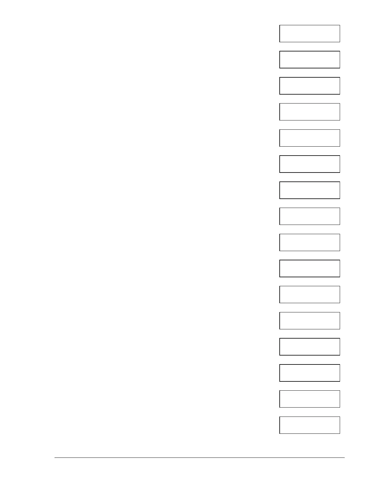
2 AAC TO C CT
PRESS LOWER KEY
30 OHM TO C-T
PRESS LOWER KEY
60 OHM TO C-T
PRESS LOWER KEY
100 OHM TO C-T
PRESS LOWER KEY
150 OHM TO C-T
PRESS LOWER KEY
200 OHM TO C-T
PRESS LOWER KEY
300 OHM TO C-T
PRESS LOWER KEY
400 OHM TO C-T
PRESS LOWER KEY
600 OHM TO C-T
PRESS LOWER KEY
800 OHM TO C-T
PRESS LOWER KEY
25 OHM TO 0-P
PRESS LOWER KEY
50 OHM TO 0-P
PRESS LOWER KEY
75 OHM TO 0-P
PRESS LOWER KEY
100 OHM TO 0-P
PRESS LOWER KEY
125 OHM TO 0-P
PRESS LOWER KEY
150 OHM TO 0-P
PRESS LOWER KEY
9355400990 Rev H DGC-500 Installation 5-17