SECTION 3
FUNCTIONAL DESCRIPTION
INTRODUCTION
This section describes how the DGC-500 functions and explains its operating features. A detailed
description of each function block is provided in the paragraphs under the heading of DGC-500 Function
Blocks.
DGC-500 operating features are described under the heading of Software Operation.
DGC-500 FUNCTION BLOCKS
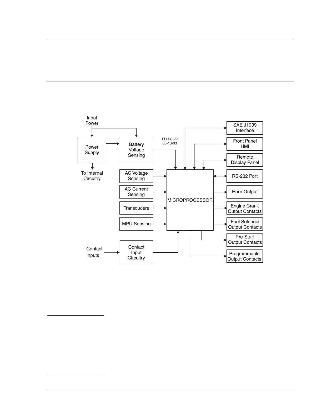
To ease understanding, DGC-500 functions are illustrated in the block diagram of Figure 3-1. The
following paragraphs describe each function in detail.
Figure 3-1. Function Block Diagram
Power Supply
The internal, switch-mode power supply uses the applied battery voltage to generate operating power for
the internal circuitry of the DGC-500. The power supply accepts a nominal battery voltage of 12 or 24 Vdc
and has an operating range of 8 to 32 Vdc. Battery voltage is applied to terminals P20 (+) and P21 (–).
Battery Voltage Sensing
Voltage applied to the power supply is filtered and reduced to a suitable level for sensing by the
microprocessor.
Microprocessor
The microprocessor controls the overall functionality of the DGC-500 and makes decisions based on
programming and system inputs.
Circuits relating to the microprocessor inputs are described in the following paragraphs.
Zero Crossing Detection
The zero crossing of A-phase to B-phase line voltage is detected and used to calculate the generator
frequency.
9355400990 Rev H DGC-500 Functional Description 3-1