Opening Settings Files
To open a DGC-500 settings file, click the Open Settings File button or click File on the menu bar and
click Open. An Open dialog box will appear and enable you to select a DGC-500 settings file (DG5
extension) for retrieval into BESTCOMS.
RS-232 CONFIGURATION
When communication is established between a PC and DGC-500, changes in BESTCOMS to the
communication configuration settings affect both the PC and DGC-500. When communication between a
PC and DGC-500 is closed, changes in BESTCOMS to the communication configuration settings affect
only the PC.
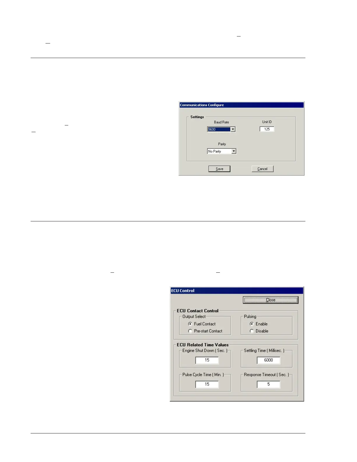
The communication configuration settings are
viewed and adjusted through the Communications
Configure dialog box. This dialog box is accessed
by clicking Configure on the menu bar and clicking
RS232. The Communications Configure dialog box
settings are illustrated in Figure 4-26 and described
in the following paragraphs.
Baud Rate. This setting selects the communication
rate. A baud rate of 1200, 2400, or 9600 can be
selected.
Parity. This setting enables and disables
summation checking of data transmitted between
the PC and DGC-500. A setting of No Parity, Odd
Parity, or Even Parity can be selected.
Unit ID. This setting allows an identification number to be assigned to a DGC-500 for polled
communication. A number between 1 and 247 may be used.
ENGINE CONTROL UNIT (ECU) INTERFACE
For J1939 applications, the interface between the DGC-500 and ECU is configurable. First, the output
contact used to power up the ECU (for non-continuously powered ECU applications) is selectable.
Second, periodic communication with the ECU (also referred to as pulsing the ECU) may be disabled if
the application requires it. Third, the timers associated with pulsing the ECU are programmable. The
settings used to configure the ECU interface are adjusted through the ECU Control dialog box. This dialog
box is accessed by clicking Configure on the menu bar and clicking ECU Control. The ECU interface
settings of the ECU Control dialog box are shown in Figure 4-27 and described below.
ECU Contact Control – Output Select. This
setting selects the DGC-500 output that is used
to power up the ECU in J1939 applications
where the ECU is not continuously powered. If
the pre-start contact is selected, the fuel contact
will still close during cranking and running of the
genset to provide a separate indication that the
genset is running.
ECU Contact Control – Pulsing. In J1939
applications where the ECU is not continuously
powered, the DGC-500 will normally pulse the
ECU periodically to update its engine monitoring
data. For applications where this periodic
pulsing is not desired, this setting allows the
pulsing feature to be disabled.
ECU Related Time Values – Engine Shut Down
(Sec.). When going from Running to Shut Down,
this setting adjusts the length of time that the
DGC-500 stays disconnected from the ECU
before starting the first pulse. The Engine Shut
Down setting range is 1 to 60 seconds.
Figure 4-26. Communications
Figure 4-27. ECU Control Dialog Box
4-24 DGC-500 BESTCOMS Software 9355400990 Rev H