1 2 3 4 5
P4
P3
P2
P37
P35
Programmable
Output 2
Programmable
Output 1
Pre-Start
GENERATOR
CIRCUIT
BREAKER
P17
P14 P11
P36 P38P33 P34
Emergency
Stop
Programmable
Input 2
Programmable
Input 3
Chassis
Ground
Contact
Sensing
Output
Relays
COM
1A
or 5A
Phase
C CT
B CT
Phase
COM
A CT
PHASE
COM
PH A
PH B
PH C
Oil Pressure
Fuel Level
Coolant Temp
Sending
Units
P40
P39
-
+
MPU
P20
P21
BATTERY
12/24 V
-
+
DGC-500
To
Bus/Load
N.C.
P30
P23
P26 P29
VOLT. VOLT. VOLT. VOLT.
NEUT.
Input 1
Programmable
P0028-11
03-03-05
3
2
4
P22
P24
P25
Horn
1
- +
P15 P12
1A
or 5A
P10
1A
or 5A
1
Sender Common
P13
P16
P18
P19
6
Magnetic
Pick-Up
1 A
5
7 7
7
7
7
6
7
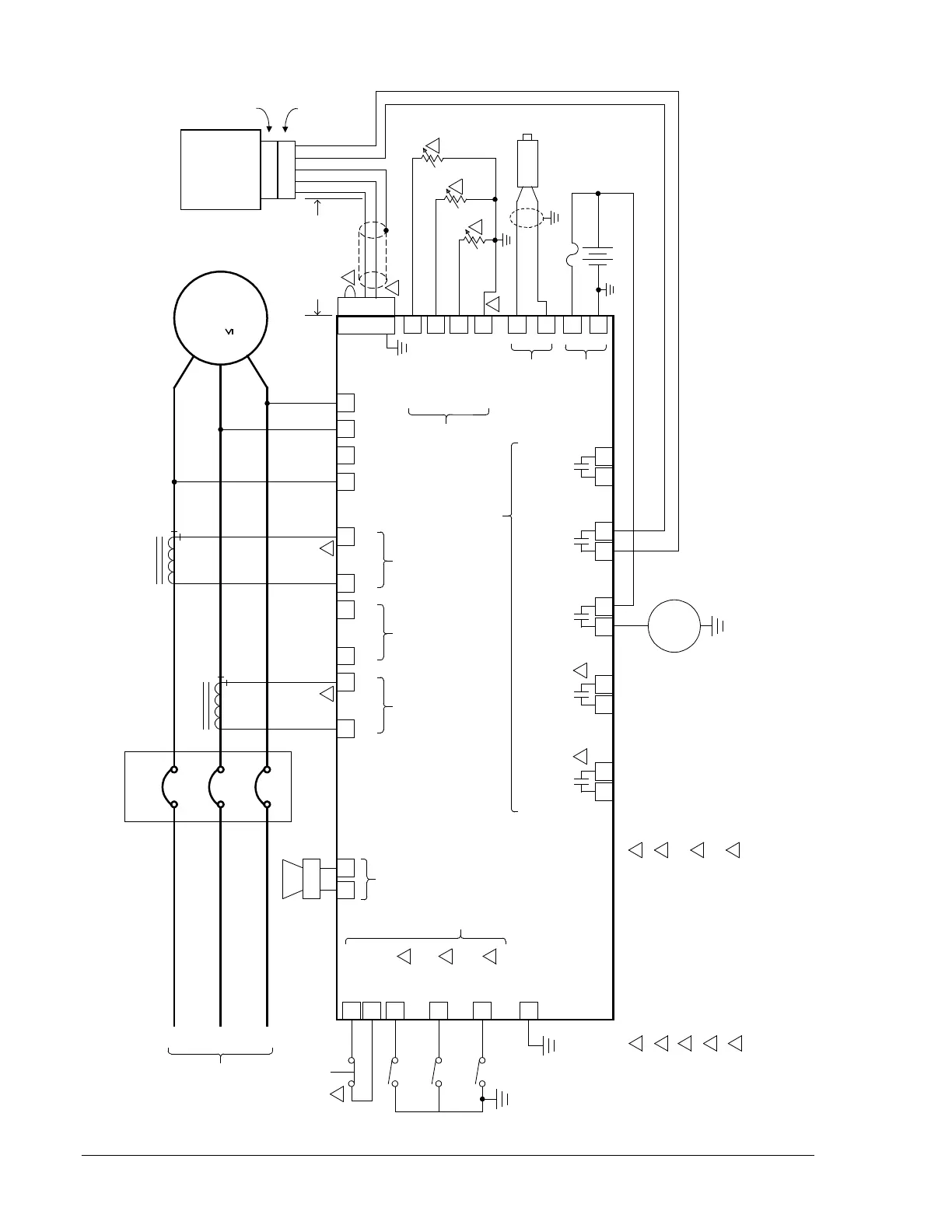
Connect near engine block (negative
battery terminal) side of senders.
Programmable input and output functions
are described in Section 3, Functional
Description.
J1939 shield should be grounded at only
one point. If grounded elsewhere, cut
J1939 shield connection to unit.
If unit is not providing one end of the
J1939 backbone, the stub connecting the
unit to the backbone should not exceed 3
feet in length.
5
Current inputs are 1 ampere or 5
ampere, depending upon style.
Mechanical oil pressure sender not
supplied by Basler.
Mechanical fuel level sender not
supplied by Basler.
Mechanical coolant temperature
sender not supplied by Basler.
Jumper terminals P35 and P37 if not
using an Emergency Stop switch.
2
3
4
1
2
3
4
5
1
2
3
4
5
Termination
Resistor
CAN High
CAN Low
VOLVO
PENTA
EDC III
GENERATOR
480V
N
L2
L1
1 2 3 4 5
Engine-
Mounted,
8-Pole,
Deutsch
Connector
Customer-
Supplied
Mating
Connector
Red
Black
Bare
J1939 Cable
Provided With Unit
8
9
Fuel
Crank
K1
N.O.
PLUGS
GLOW
K1
Com
K2
N.O.
K2
Com
K5
N.O.
K5
Com
+
1
8
9