Baumer Electrical installation | 6
V1.0 | IDC200 Operating Manual 35
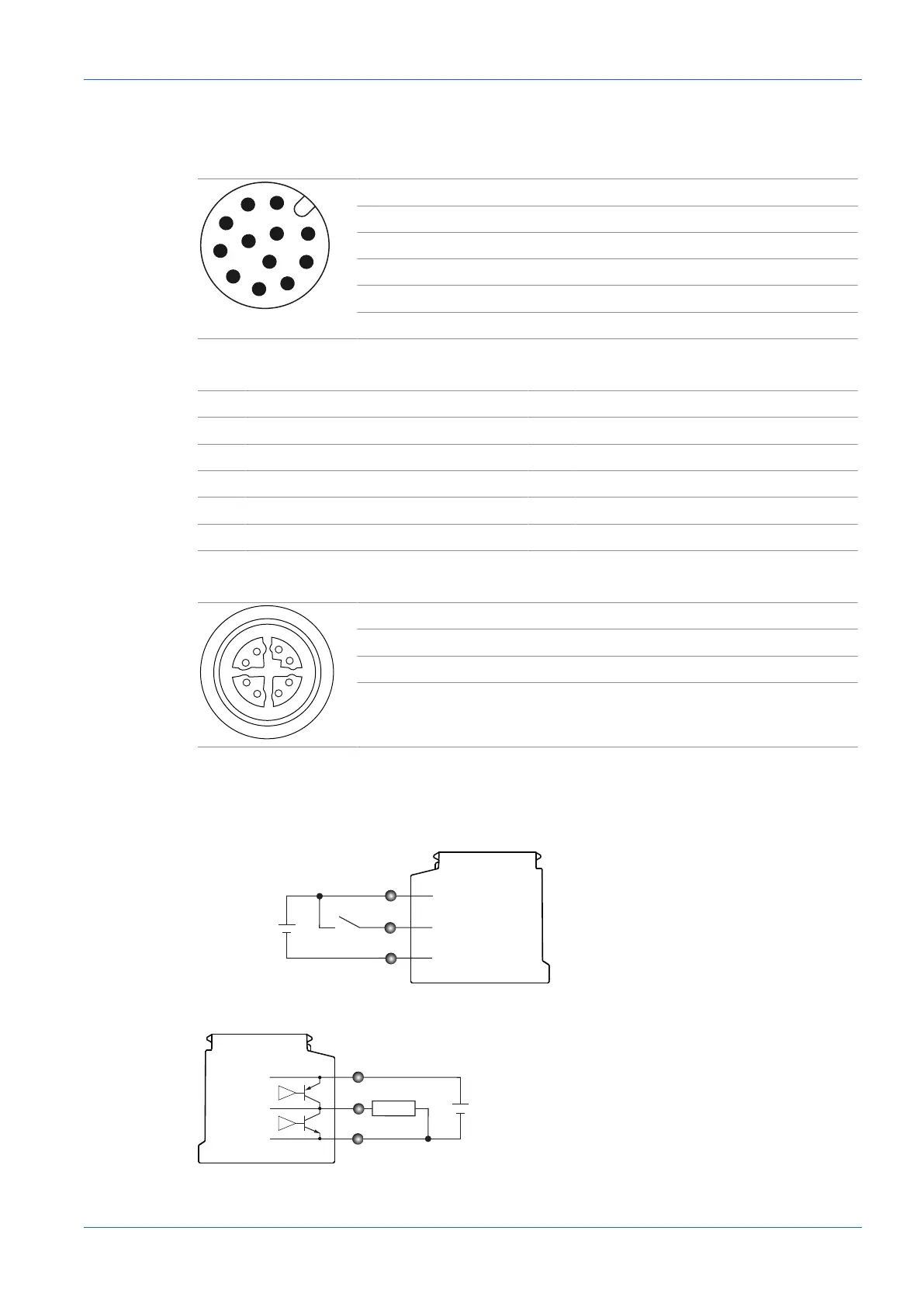
6.3 Pin assignment
Power Supply / Digital-IO
1 Power (+24 VDC ±20%) 2 Ground
3 IN1 (Trigger) 4 IN2
5 IN3 6 OUT1
7 (not used) 8 OUT2
9 OUT3 10 (not used)
11 (not used) 12 (not used)
Wire colors according to DIN IEC 757
1 BN – Brown 2 BU – Blue
3 WH – White 4 GN – Green
5 PK – Pink 6 YE – Yellow
7 BK – Black 8 GY – Grey
9 RD – Red 10 VT – Violet
11 GY-PK – Grey Pink 12 RD-BU – Red Blue
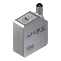
Industrial Ethernet
1 RX+ 2 RX-
3 TX+ 4 TX-
5 -VDC 6 -VDC
7 +VDC 8 +VDC
6.4 Wiring
Input
GND
Power
IN 1 (Trigger)
Sensor
+ 18 ...+ 30 VDC
-
1
3
2
Output
Sensor
1
6
2
+ 18 ...+ 30 VDC
GND
Power
OUT 1
-