Baumer Description | 3
V1.0 | IDC200 Operating Manual 9
3 Description
3.1 Sensor
3.1.1 Structure
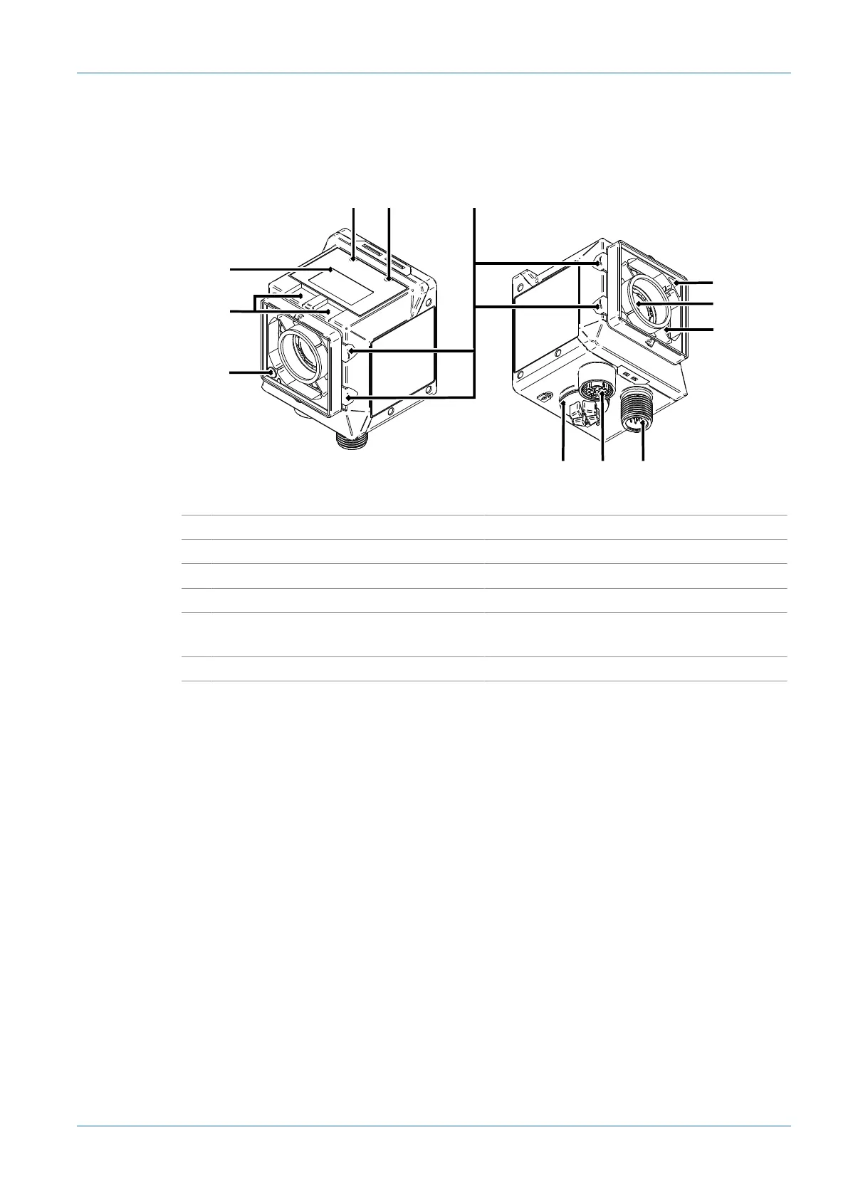
Ill.1: Sensor design
1 Pointer (positioning aid) 2 qTeach Buttons
3 Display 4 LED Link
5 LED Power 6 Illuminated ring (4 x RGB LED indicators)
7 Sensor (filter recognition) 8 Camera (with electromechanical focus)
9 Internal illumination (each segment to be
switched on individually)
10 Electrical connection; 12-pin M12, A-en-
coding
11 Ethernet connection (1 GigE); X-encoding 12 USB-C connection with blind plug