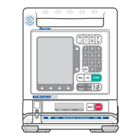
07-19-B1-688 FLO-GARD 6201 VOLUMETRIC INFUSION PUMP SERVICE MANUAL 7-21
Troubleshooting Troubleshooting Chart
The Battery Icon is lit while pump is
running on AC.
Check the tightness of the power plug
into the AC outlet.
Check the rear power fuses under the
power cord cover.
Check the AC outlet for proper
voltage.
Check the line cord for continuity.
Check power supply for proper
voltage per “Automatic Test Mode 1:
Calibration Mode 1” on page 9-14.
Check connectors CNAC, CN301 and
CNBUS1/CNBUS2 for proper
connection and continuity.
Press the power plug firmly into the
grounded AC outlet.
Replace the fuse(s) when it has failed
and recharge the battery.
When the voltage is below 105 VAC,
connect the pump to the correct
supply voltage.
Connect the power terminals of the
power plug to an ohmmeter. The
ohmmeter should indicate continuity.
Replace Power Supply board.
Replace CPU board.
Replace Sensor board.
The Plug Icon is not lit when the
pump is plugged in to AC power
Check the tightness of the power plug
into the AC outlet.
Check the rear power fuses under the
power cord cover.
Check the AC outlet for proper
voltage.
Check the line cord for continuity.
Press the power plug firmly into the
grounded AC outlet.
Replace the fuse(s) when it has failed
and recharge the battery.
When the voltage is below 105 VAC,
connect the pump to the correct
supply voltage.
Connect the power terminals of the
power plug to an ohmmeter. The
ohmmeter should indicate continuity.
The Battery Icon is off while pump is
running on internal battery.
Turn pump off and back on. If failure recurs, replace Display
board. Replace CPU board.
The backlight is off when the pump is
running on internal battery power.
N/A Press the BACKLIGHT key as long
as required to view the pump settings.
ALARM and ALERT LEDs are lit but
the pump does not operate.
Check backup battery voltage in
accordance with “Automatic Test
Mode 1: Calibration Mode 1” on page
9-14.
Sometimes this condition is followed
by a F49 and/or F94 code. Recharge
or replace the battery to clear the
condition.
Electrical Issues
The LCDs are blank, indicate
irrational display or have missing
segments.
Check ICP301 and CNDISP for
proper connection and continuity
using Test Mode 5 (“Automatic Test
Mode 5: Display Check Mode” on
page 7-10).
Install LCD Cushions, if necessary.
See “LCD Cushion Installation” on
page 8-30.
Replace CPU board.
Replace Sensor board.
Replace Display board.
The backlight does not light. N/A Replace Display board.
Table 7-4 Troubleshooting Chart — continued
Symptom Checks Corrective Action


 To Next Page