BDCOM S6508 Switch Hardware Installation Guide
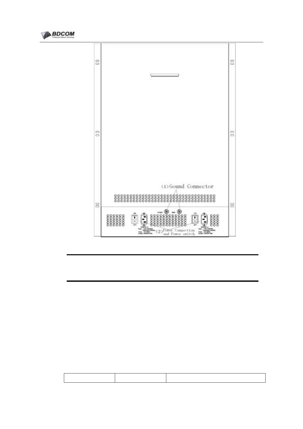
Figure 1-4 S6508 Rear View
(1)
Gound Connector: System Gound Connector.
(2)
Power Connection and Power switch: The System Power supply’s Power
Connection and Power switch.
1.4.3 System module Slots
System module Slots include the slot guides and the backplane.
The S6508 chassis have 10 system module Slots, the space between the two near
Slots is 40mm. The slots is vertical.The Slots number is ordinal, from left to right is Slot
1 to Slot 9. The Slot 5 and the Slot 6 are MSU Slots that only support the LS6508-MSU,
and other modules must not be pluged in. Slot 1-4 and Slot 7-10 are LPU Slots that
support the other S6508 Switching modules.
The following Table1-1 describes the System Slots support module.
Table 1-1 System Slots Sopport module Decription
Slot number Slot Name Support module name
- 6 -