89000046-014 KSN 780/8XX/900 AeroNav AML STC Installation Manual for Helicopters
Rev 0 Page 6-7
© Honeywell International Inc. Do not copy without express permission of Honeywell.
6.1.6 Heading Input
Note: This section is N/A for the AeroNav 880/780.
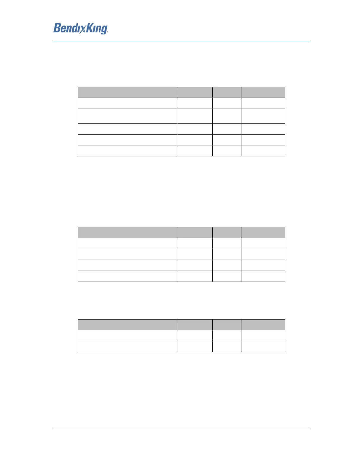
The AeroNav XXX can accept a 3-wire ARINC 407 Synchro heading input on the following connectors
and pins:
Synchro X P1002 10 Input
Synchro Reference Signal + (26VAC
400 Hz)
P1002 13
Input
Synchro Y P1002 23 Input
Synchro Z P1002 24 Input
Synchro Reference Signal - (GND) P1002 25 Input
Table 42 Synchro Heading Input
6.1.7 Main Course Deviation Indicator Output
The main indicator displays both lateral and vertical deviations, TO/From, and Flag indications from
the NAV and GPS receivers.
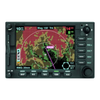
6.1.7.1 Lateral/Vertical Deviations
The lateral and vertical deviations are on the following connector and pins:
Main +Left P1001 21 Output
Main +Right P1001 22 Output
Main +Up P1001 27 Output
Main +Down P1001 28 Output
Table 43 Main Course Deviation Output
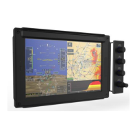
6.1.7.2 TO/FROM Indication Flag
The To/From Flag indication flags are on the following connector and pins:
Main +To P1001 25 Output
Main +From P1001 26 Output
Table 44 Main TO/From Flag Output