KB (E4 + E6) 02/2017 page 25/148
5. Start up
After connecting the electrical supply (chap. 4.1), turn on the chamber by the main power switch (1). The
pilot lamp shows the chamber is ready for operation.
Observe a delay time of about 30s between turning Off and On again. Otherwise an initializa-
tion problem may occur.
Note that the chamber is in stand-by mode when the main power switch has been turned on and yet the
controller display is dark. Turn on the chamber by pressing any controller button.
Warming chambers may release odors in the first few days after commissioning. This is not a quality de-
fect. To reduce odors quickly we recommend heating up the chamber to its nominal temperature for one
day and in a well-ventilated location.
WARNING: If customer should use a BINDER chamber running in non-supervised continu-
ous operation, we strongly recommend in case of inclusion of irrecoverable specimen or
samples to split such specimen or samples and store them in at least two chambers, if this is
feasible.
6. Functional overview of the T4.12 chamber controller
The T4.12 chamber controller controls the temperature (range: 4 °C up to 100 °C) and the fan speed
(range: 40 % up to 100 %) inside the chamber. You can enter the desired set point values in fixed value
operating mode or in program mode in the display controller. The controller also offers a week program
function and various notifications and alarm messages with visual and audible indication, a trace file and
remote alarms via e-mail. You can enter values or programs directly at the controller keypad or using the
APT-COM™ 3 DataControlSystem software (option, chap. 19.1) specially developed by BINDER.
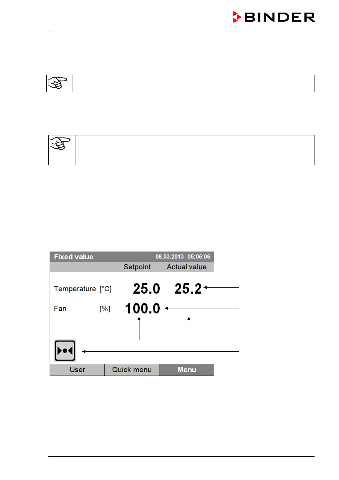
Temperature values
Fan speed value
Actual values
Set-point values
Icons:
Controller operating in “fixed
value” operating mode
Figure 12: T4.12 microprocessor controller, initial view in “fixed value” controller mode (sample values)