Biotage
®
Selekt User Manual | © Biotage 2020
Troubleshooting
»
UV detector error during UV Zero.
The problem may be due to:
»
Contaminated flow cell. Clean the
flow cell; see page 31.
»
Highly absorbing solvent(s).
Choose less absorbing solvent(s).
»
Sample in the flow cell. Flush the system
(see page 23) and retry performing the run.
»
The UV detector needs to be recalibrated; see page 30.
Leak Detected
See “Leaks” on page 32.
Overpressure Detected
Blockage due to precipitate or kinked tubing
Warning
»
Shut down the system before replacing any tubing. Use only
tubing designed for the Selekt system and supplied by Biotage.
1. Once the pressure has decreased to ambient pressure (the
current pressure is displayed in the top left corner of the
software), shut down the system (see page 18).
Note: If the pressure does not reach ambient within
a few minutes, release the contained pressure as
described in “Restart after power failure or shutdown with
overpressure” below.
2. If applicable, straighten or replace kinked tubing.
Only replace tubes with the equivalent tubes designed
for the Selekt system and supplied by Biotage.
3. Visually inspect all tubing for precipitation. If found,
remove and clean the tubing.
4. Visually inspect the flow cell for precipitation. If found,
clean the flow cell (see page 31).
5. Turn on the system.
The flow rate is too high for a purification or flush
1. If the overpressure occurred during a flush, press Purge
in the Flushes and Purge view. Once the pressure has
decreased to ambient pressure (the current pressure is
displayed in the top left corner of the software), start a new
flush at a lower flow rate.
2. If the overpressure occurred during a run, lower the flow rate
and resume the run. The system will wait until the pressure
has decreased to an acceptable level before proceeding with
the run using the lower flow rate.
Restart after power failure or shutdown with overpressure
Warning
»
When releasing a stuck check valve, there is a risk of a small
amount of solvent splashing out.
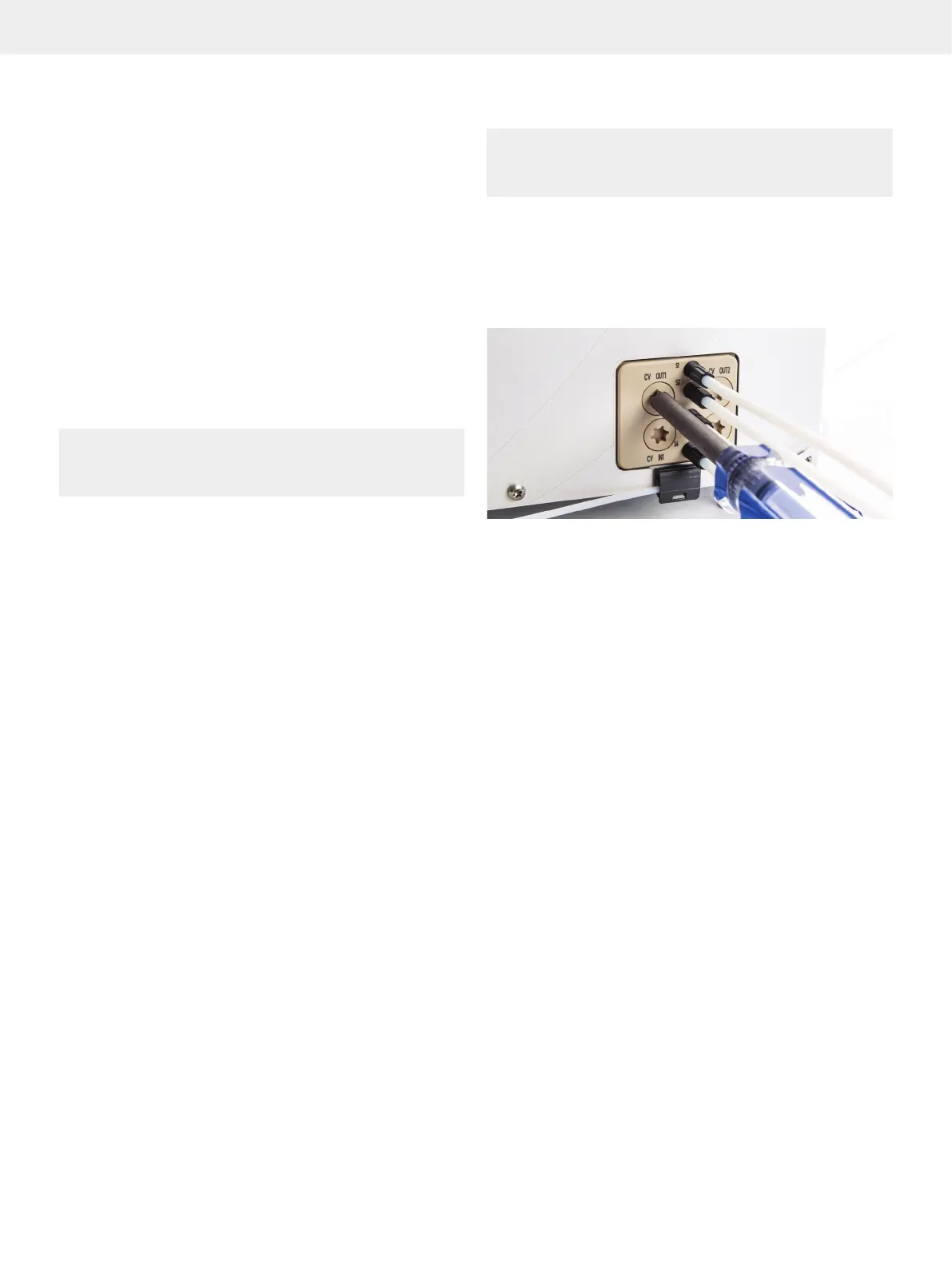
1. Release the pressure by slowly unscrewing the check
valve cap from one of the CV OUT valves using the Torx 50
screwdriver supplied with the system; see Figure 64.
2. Once the pressure has been reduced to ambient pressure
(the current pressure is displayed in the top left corner of the
software), fasten the check valve cap.
Figure 64. Removing the check valve cap from one of the CV OUT valves.
Pump-Related Problems
Note: If using highly volatile (i.e. high vapor pressure) solvents
such as DCM, reservoir elevation is strongly recommended.
Have all solvents on the same physical height to improve
accuracy in the solvent mixing. It is also highly advisable to
reduce the max aspiration rate (see “Administrate Solvents”
on page 25) and, if possible, lower the ambient temperature.
See “Solvent Specifications” on page 38 for the vapor
pressure of different solvents.
»
Air bubbles moving through the column inlet tubing in a
steady stream during solvent delivery may be due to:
»
Little or no solvent in the lines. Refill the solvent
reservoir(s) and ensure that all used solvent
inlet lines are submerged in solvent (see
“Prime the Solvent Inlets” on page 7).
»
One or more solvent inlet lines are loose.
Check fittings and tighten if necessary.
»
One or more solvent inlet filters are clogged. Sonicate
or replace the solvent inlet filters; see page 34.
Note that particulate-free solvent is required and that
re-circulating of the solvent is not recommended.
»
Solvent cavitation or degassing during aspiration
stroke. Possible solutions are: 1. Elevate
the solvent reservoirs. 2. Lower the ambient
temperature. 3. Sonicate or replace the solvent
inlet filters; see page 34. 4. Reduce the
max aspiration rate for the used solvents; see
“Administrate Solvents” on page 25.