Prepare the System
Mount a Biotage
®
SNAP XL
Column (Optional)
Warning
»
Always use Biotage Safety Valve (P/N 417115SP) when
processing columns or combinations (e.g. column and dry
load vessel) with a total CV larger than 0.8 L.
»
Never use columns or combinations with a total CV larger
than 3.1 L.
»
Do not over-tighten the fittings or the tubing may become
damaged.
Note: When using SNAP XL columns, it is not possible to have
the optional secondary solvent containment placed on top of
the system.
Mount the Biotage
®
SNAP XL Column Holder
The Biotage
®
SNAP XL column holder must be ordered
separately (P/N 412422).
1. Slide one screw (see A in Figure 12) into one of the two
lower rails on the right side of the system.
2. Slide the column holder into position with the fastening
bracket (see B in Figure 12) in the same rail as the screw.
3. Slide the other screw into the same rail.
4. Lock the column holder in the desired position using the
two screws; see the column holder to the right in Figure 12.
Note: The top screw is used for adjusting the column holder to
the length of the used column.
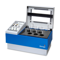
Figure 12
CC
AA
BB
DD
. SNAP XL column holder. A: Holder screws. B: Fastening
bracket. C: Bottom column loop. D: Top column loop.
Mount the Biotage
®
SNAP XL Column
Two SNAP XL fittings with Luer connections are required and
must be ordered separately; see Figure 14 on page 6.
1. Remove the stoppers from the top and bottom of the column.
2. Place the column in the bottom loop on the column holder
(see C in Figure 12) and then unfasten and lower the top loop
(see D in Figure 12) until it is in contact with the column (see
Figure 13). Tighten the screw.
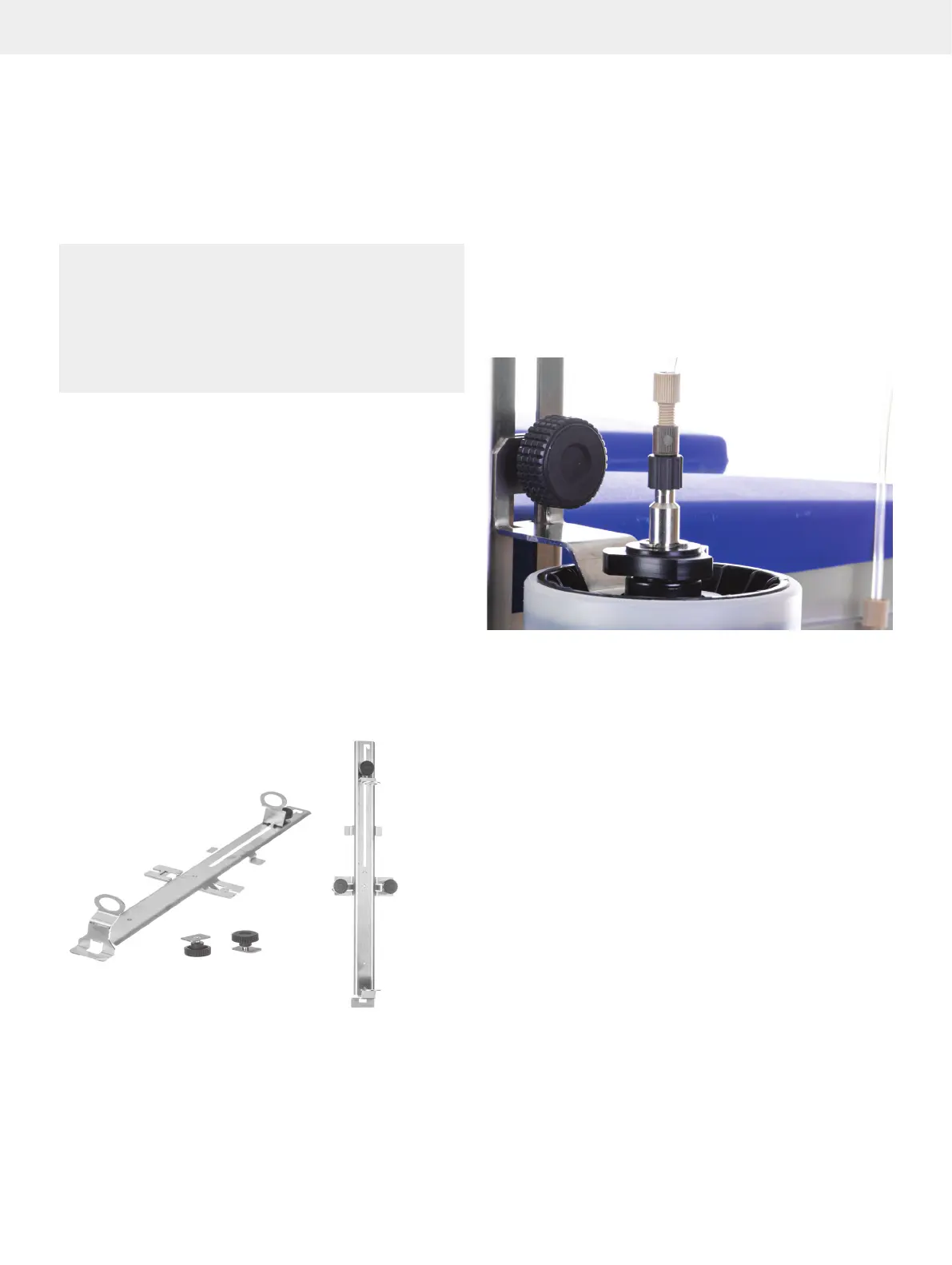
Figure 13. The top screw is used for adjusting the column holder to the
length of the used column.
3. Fasten the SNAP XL fittings to the top and bottom of the
column; see Figure 14 on page 6.
4. Connect the tubing leading from the C1 or C2 port on the right
side of the system (see Figure 15 on page 6), depending
on which channel you want to use, to the connection at the
bottom of the safety valve (see C in Figure 11).
5. Connect the tube leading from the connection at the top of
the safety valve (see D in Figure 11) to the Luer fitting at the
top of the column.
6. Connect the tubing leading to the R1 or R2 port on the right
side of the system (see Figure 15 on page 6), depending
on which channel you want to use, to the Luer fitting at the
bottom of the column.
7. Insert the drain tube (see A in Figure 11) into the waste
reservoir.