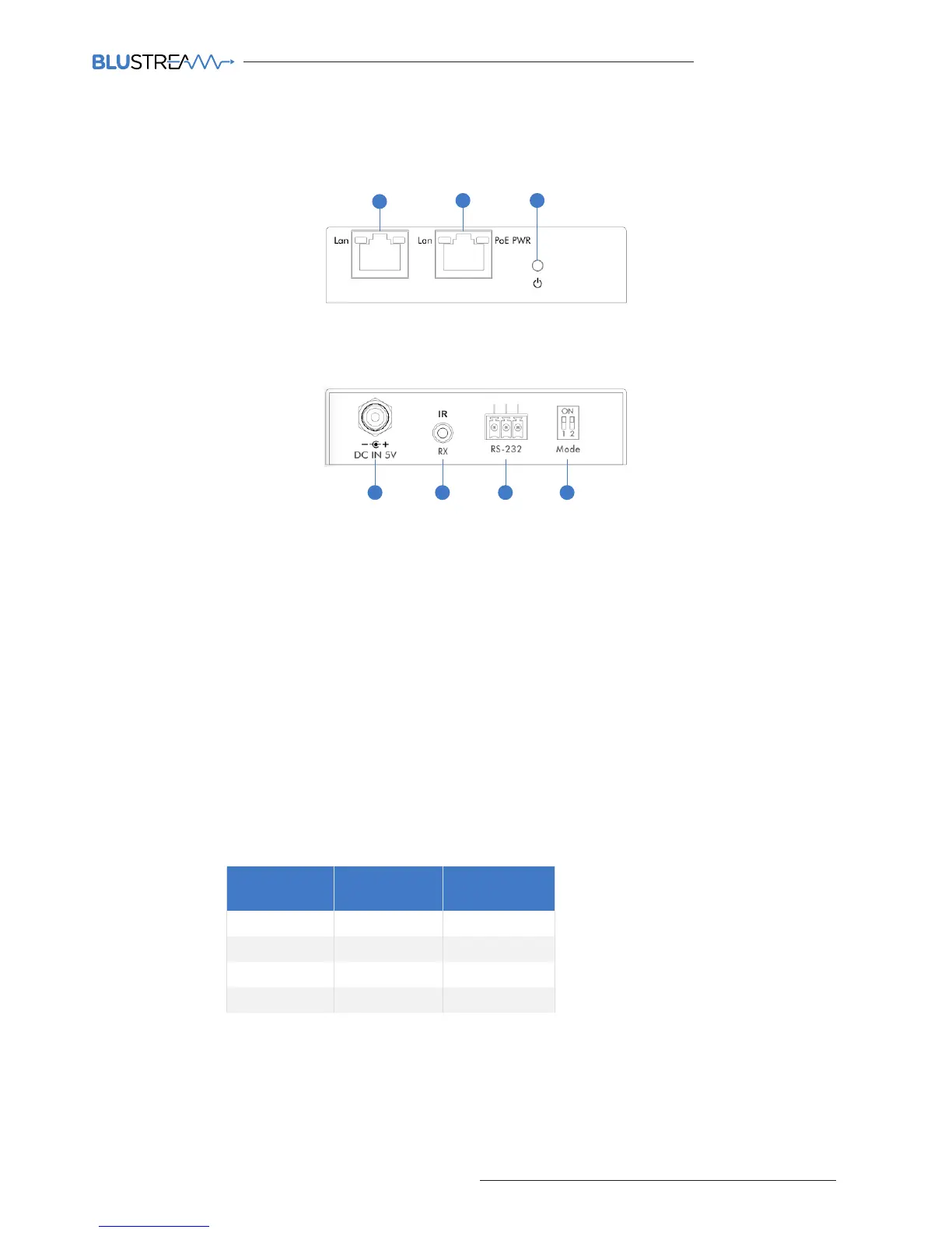
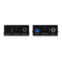
CM100 Front Panel
7654
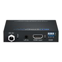
1 Control LAN port - Connect to existing network that your third party control system resides on. The Control LAN
port is used for Telnet/IP control of the Multicast system
2 Multicast Video LAN port - Connect to the layer 3 network switch that the Blustream Multicast components are
connected to
3 Power LED indicator
4 Power port – Use 5V 1A DC adaptor (sold separately) if not using a PoE network switch
5 IR RX (IR input) – 3.5mm stereo jack. Connect to third party control system if you are using IR as your method of
controlling the Multicast system. Please use supplied Blustream IRR 5V IR Receiver. When using the Blustream
IRCAB cable (optional) ensure cable direction is correct.
Note: Only basic switching commands are available when using IR as a method of control. Advance Multicast
features are only available using Telnet/IP and RS-232
6 RS-232 control port – Connect to a third party control device for control of the Multicast system using RS-232
7 Mode dip-switches - Used for adjusting the RS-232 control port baudrate settings as per the chart below.
Note - If changing the Baudrate settings of the CM100 you must power cycle the unit for these to update
CM100 Rear Panel
Panel Description - CM100 Control Module
21 3
CONTROL LAN VIDEO LAN
Data Bit: 8-bit
Parity: None
Stop Bit: 1-bit
Flow Control: None
Baudrate
Mode Dip-
Switch 1
Mode Dip-
Switch 2
9600 Down Down
19200 Down Up
57600 Up Down
115200 Up Up