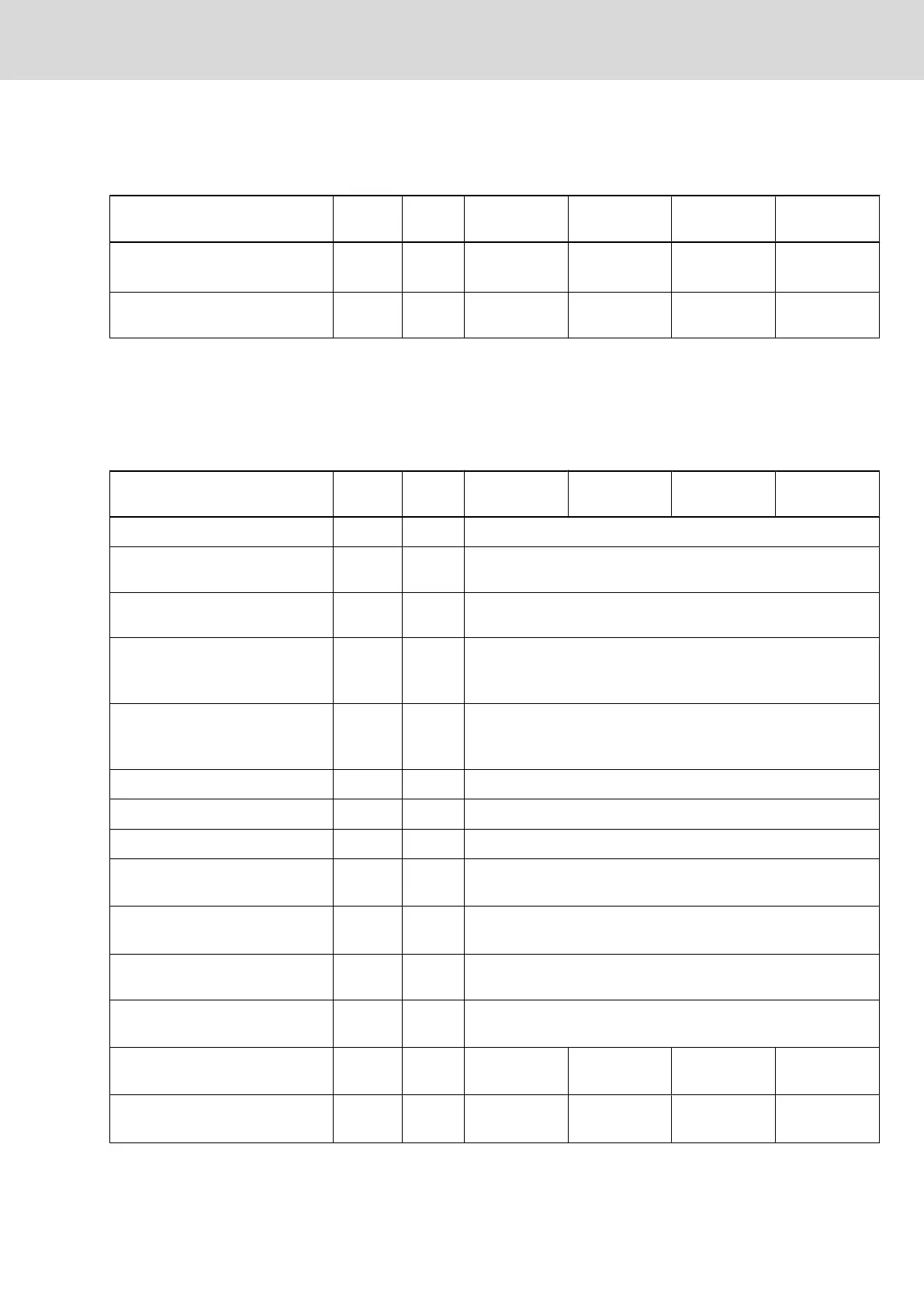
External Braking Resistor
Requirements on external braking resistor
Description Symbol Unit
HCS03.1E-
W0070-_-05
HCS03.1E-
W0100-_-05
HCS03.1E-
W0150-_-05
HCS03.1E-
W0210-_-05
minimum required resistance value
of external braking resistor
1)
R
DC_Bleed‐
er
ohm 17,5 11,7 7,0 5,0
assigned braking resistor type
HLR01
2)
HLR01.1N-030
0-N17R5
HLR01.1N-047
0-N11R7
HLR01.1N-078
0-N07R0
HLR01.1N-1K
08-N05R0
1) see Parameter Description "P‑0‑0858, Data of external braking resistor"
2) see also Project Planning Manual "Additional Components"; see Pa‐
rameter Description "P‑0‑0858, Data of external braking resistor"
Fig.5-70: HCS - Requirements on external braking resistor
Inverter
Data of power section - Inverter
Description Symbol Unit
HCS03.1E-
W0070-_-05
HCS03.1E-
W0100-_-05
HCS03.1E-
W0150-_-05
HCS03.1E-
W0210-_-05
allowed switching frequencies
1)
f
s
kHz 4, 8, 12, 16
output voltage, fundamental wave
with open-loop operation
U
out_eff
V ~ UDC x 0,71
output voltage, fundamental wave
with closed-loop operation
U
out_eff
V ~ UDC * 0,71
rise of voltage at output with
U
LN_nenn
and 15 m motor cable
length phase-phase (10‑90%)
2)
du/dt kV/µs 5,00
rise of voltage at output with
U
LN_nenn
and 15 m motor cable
length phase-ground (10‑90%)
3)
du/dt kV/µs 5,00
output frequency range at f
s
= 2 kHz f
out_2k
Hz -
output frequency range at f
s
= 4 kHz f
out_4k
Hz 0...400
output frequency range at f
s
= 8 kHz f
out_8k
Hz 0..800
output frequency range at
f
s
= 12 kHz
f
out_12k
Hz 0..1200
output frequency range at
f
s
= 16 kHz
f
out_16k
Hz 0...1600
output frequency threshold to de‐
tect motor standstill
4)
f
out_still
Hz 2...4
maximum output current at
f
s
= 2 kHz
I
out_max2
A -
maximum output current at
f
s
= 4 kHz
I
out_max4
A 70,0 100,0 150,0 210,0
maximum output current at
f
s
= 8 kHz
I
out_max8
A 62,0 86,0 137,0 190,0
Project Planning Manual | Rexroth IndraDrive Electric Drives
and Controls
| Bosch Rexroth AG 85/369
Power Sections for Converters - IndraDrive C
 Loading...