Description Symbol Unit
HCS03.1E-
W0070-_-05
HCS03.1E-
W0100-_-05
HCS03.1E-
W0150-_-05
HCS03.1E-
W0210-_-05
maximum output current at
f
s
= 12 kHz
I
out_max12
A 47,0 60,0 105,0 135,0
maximum output current at
f
s
= 16 kHz
I
out_max16
A 34,0 50,0 86,0 105,0
allowed continuous output current
at f
s
= 2 kHz
I
out_cont2
A -
allowed continuous output current
at f
s
= 4 kHz
I
out_cont4
A 45,0 73,0 95,0 145,0
allowed continuous output current
at f
s
= 8 kHz
I
out_cont8
A 33,0 50,0 66,0 100,0
allowed continuous output current
at f
s
= 12 kHz
5)
I
out_cont12
A 24,0 37,0 48,0 72,0
allowed continuous output current
at f
s
= 16 kHz
6)
I
out_cont16
A 18,0 27,0 37,0 54,0
allowed continuous output current
at f
s
= 2 kHz; output frequency
f
out
< f
out_still
I
out_cont0Hz_
2
A -
allowed continuous output current
at f
s
= 4 kHz; output frequency
f
out
< f
out_still
I
out_cont0Hz_
4
A 29,2 46,9 60,9 92,5
allowed continuous output current
at f
s
= 8 kHz; output frequency
f
out
< f
out_still
I
out_cont0Hz_
8
A 18,3 30,4 39,6 57,8
allowed continuous output current
at f
s
= 12 kHz; output frequency
f
out
< f
out_still
7)
I
out_cont0Hz_
12
A 12,0 20,8 27,4 38,3
allowed continuous output current
at f
s
= 16 kHz; output frequency
f
out
< f
out_still
8)
I
out_cont0Hz_
16
A 8,6 15,0 20,0 27,9
assigned output filters at nom. da‐
ta; f
s
= 4 kHz
tbd
1) also depending on firmware and control section; see Parameter De‐
scription "P‑0‑0001, Switching frequency of the power output stage"; see
"P-0-4058, Amplifier type data"
2) 3) guide value, see following note
4) see following note regarding reduction output current
5) 6) 7) 8) see Parameter Description "P‑0‑0556, Config word of axis controller",
load-depending reduction of PWM frequency fs
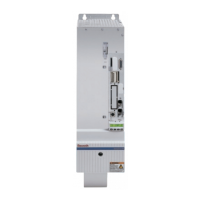
Fig.5-71: HCS - Data of power section - Inverter
86/369 Bosch Rexroth AG | Electric Drives
and Controls
Rexroth IndraDrive | Project Planning Manual
Power Sections for Converters - IndraDrive C
 Loading...